Transmission
DISASSEMBLY1. Remove transmission from vehicle.
2. Install a suitable tail shaft housing plug to avoid contaminating internal components with cleaning solvents.
3. Clean exterior of transmission with suitable solvent or pressure washer.
4. Remove torque converter from transmission.
5. Remove throttle and shift levers from valve body manual shaft and throttle lever shaft.
Fig. 73:
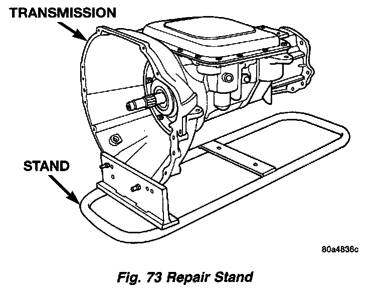
6. Mount transmission in repair stand C-3750-B or similar type stand.
7. Remove extension housing.
8. Remove fluid pan.
Fig. 74:
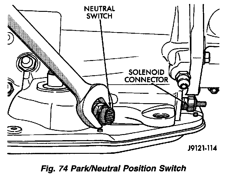
9. Remove [1][2]park/neutral position switch and seal.
10. Remove valve body.
Fig. 75:
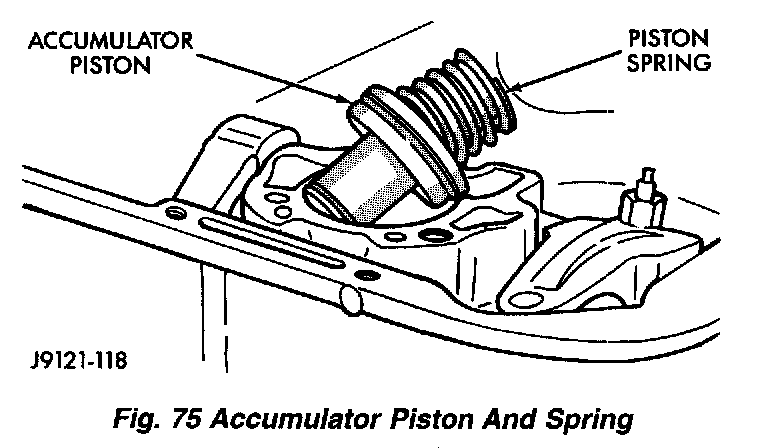
11. Remove accumulator spring and piston.
Fig. 76:
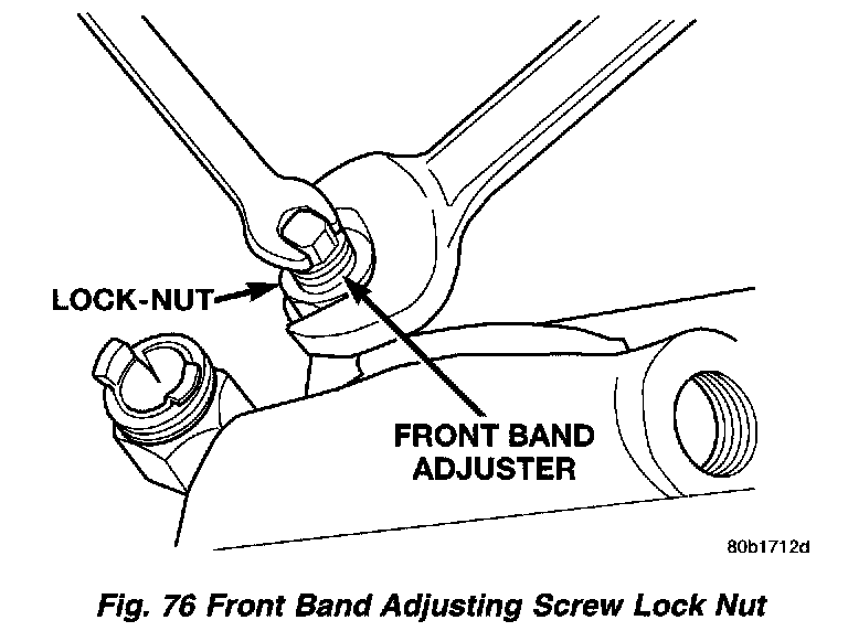
12. Loosen front band adjusting screw lock nut 4 - 5 turns. Then tighten band adjusting screw until band is tight around front clutch. This prevents front/rear clutches from coming out with pump and possibly damaging clutch or pump components.
13. Remove oil pump bolts.
Fig. 77:
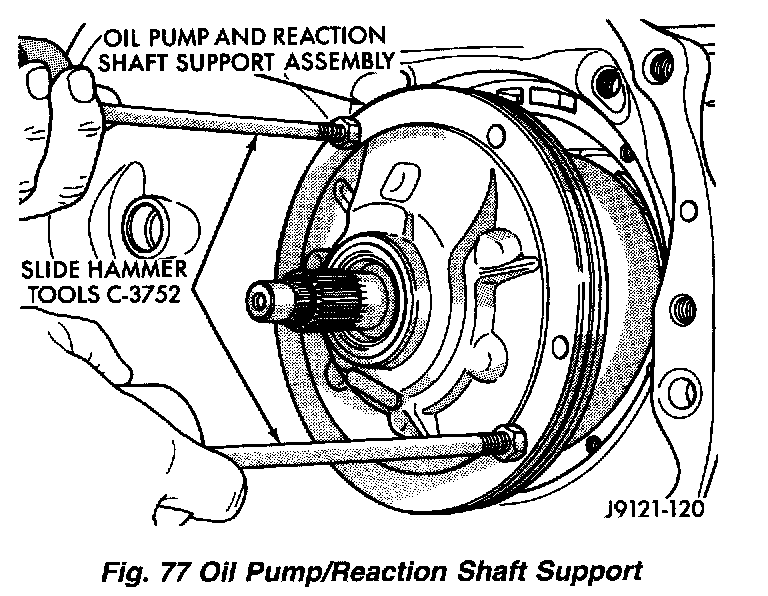
14. Thread bolts of Slide Hammer Tools C-3752 into threaded holes in pump body flange.
15. Bump slide hammer weights outward to remove pump and reaction shaft support assembly from case.
16. Loosen front band adjusting screw until band is completely loose.
Fig. 78:
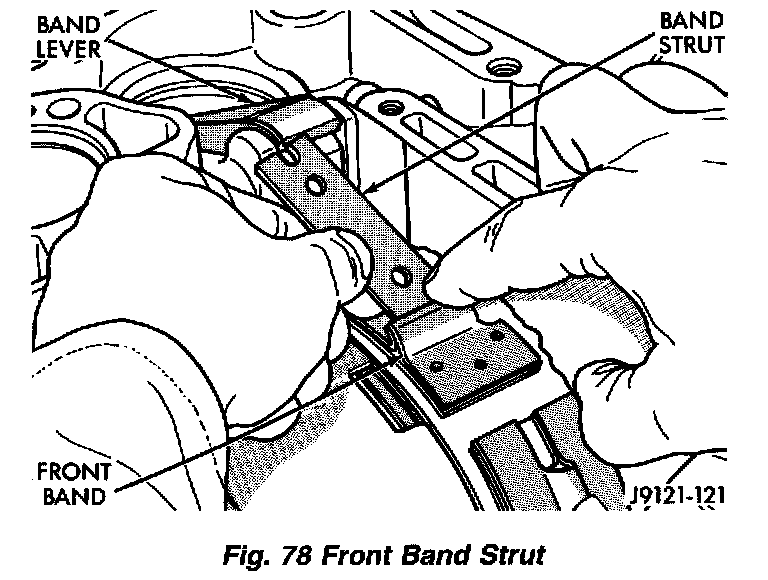
17. Squeeze front band together and remove band strut.
Fig. 79:
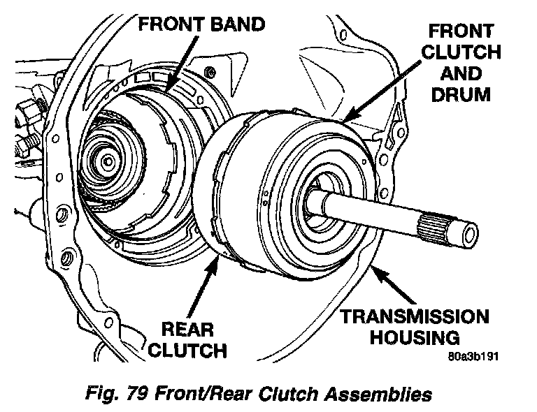
18. Remove front and rear clutch units as an assembly. Grasp input shaft, hold clutch units together and remove them from case.
Fig. 80:
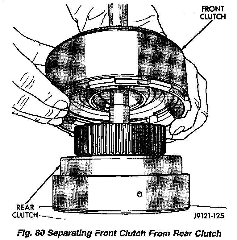
19. Lift front clutch off rear clutch. Set clutch units aside for overhaul.
Fig. 81:
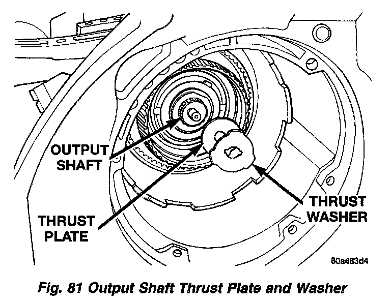
20. Remove output shaft thrust washer from output shaft (or from rear clutch hub.
21. Remove output shaft thrust plate and washer from output shaft hub.
Fig. 82:
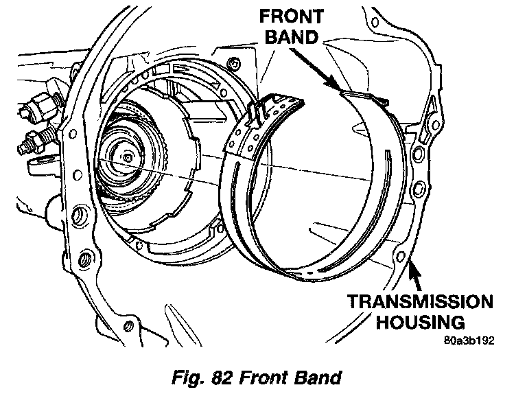
22. Remove front band from case.
23. Remove extension housing from transmission case.
24. Remove governor body and park gear from output shaft.
Fig. 83:
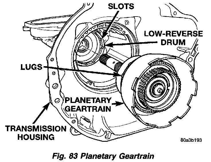
25. Remove output shaft and planetary gear-train as assembly. Support gear-train with both hands during removal. Do not allow machined surfaces on output shaft to become nicked or scratched.
Fig. 84:
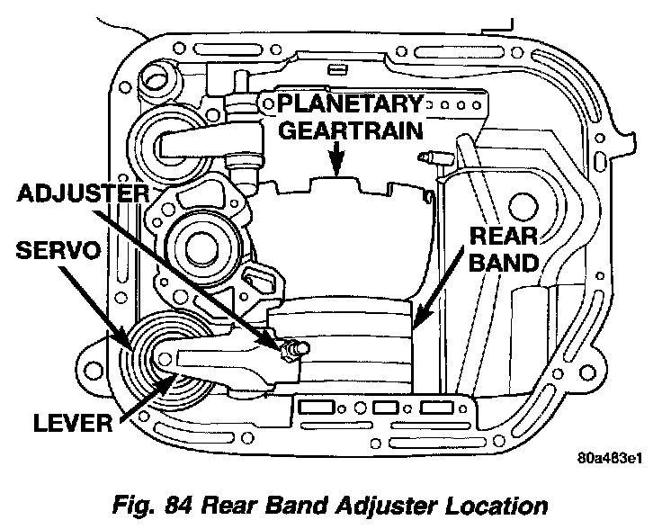
26. Loosen rear band adjusting screw 4 - 5 turns.
Fig. 85:
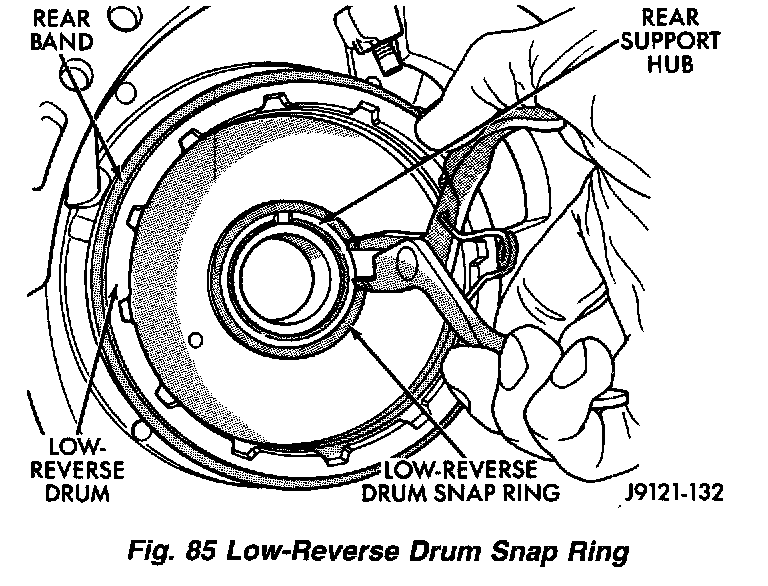
27. Remove snap ring that secures low-reverse drum to rear support hub, however do not remove drum.
Fig. 86:
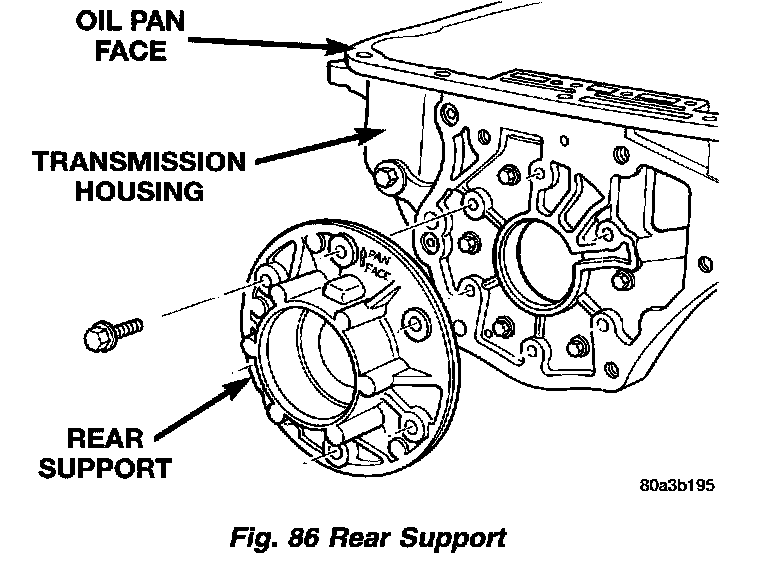
28. Remove bolts attaching rear support to transmission case and pull support from low-reverse drum.
Fig. 87:
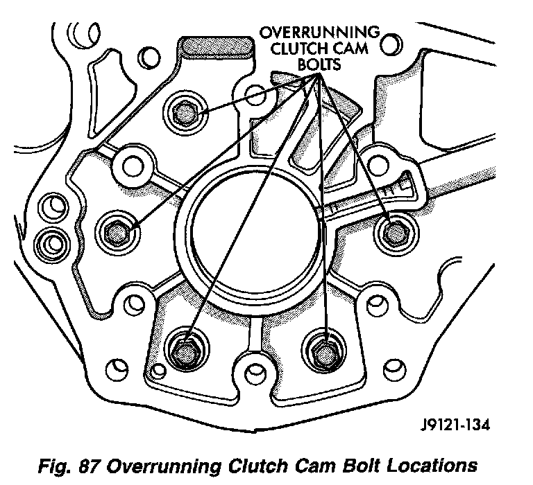
29. Remove bolts attaching overrunning clutch cam and low-reverse drum to transmission case.
30. Using snap-ring plier, pull rear band anchor pin (located on the servo side of the rear support) from transmission case.
Fig. 88:
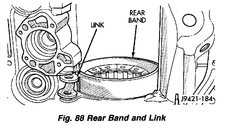
31. Remove rear band and link from transmission.
Fig. 89:
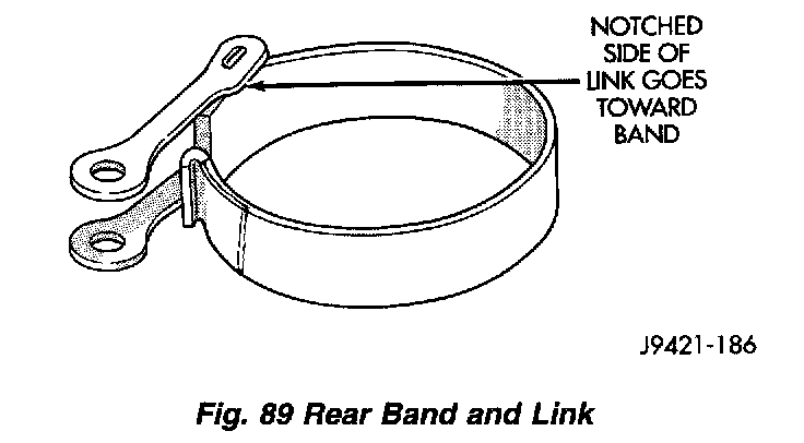
32. Separate link from rear band.
33. If necessary remove front and rear band servo levers. All transmission components can be serviced without removing the levers.
Fig. 90:
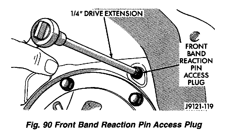
a. Using a 1/4 inch drive extension remove front band reaction pin access plug.
Fig. 91:
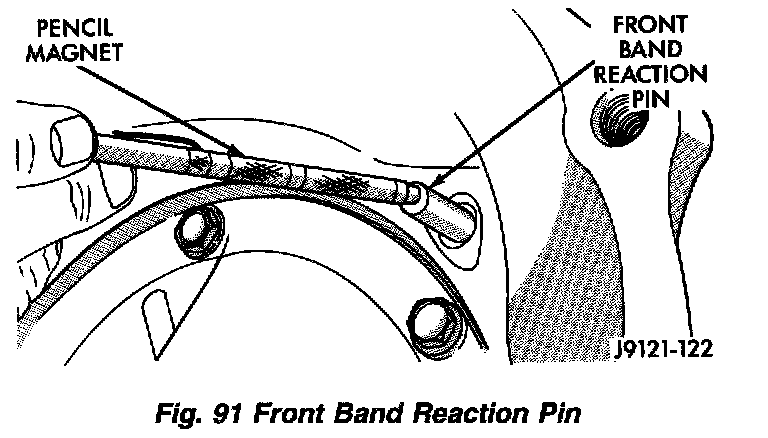
b. Remove front band reaction pin with pencil magnet. Pin is accessible from converter housing side of case.
Fig. 92:
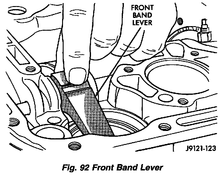
c. Remove front band lever.
Fig. 93:
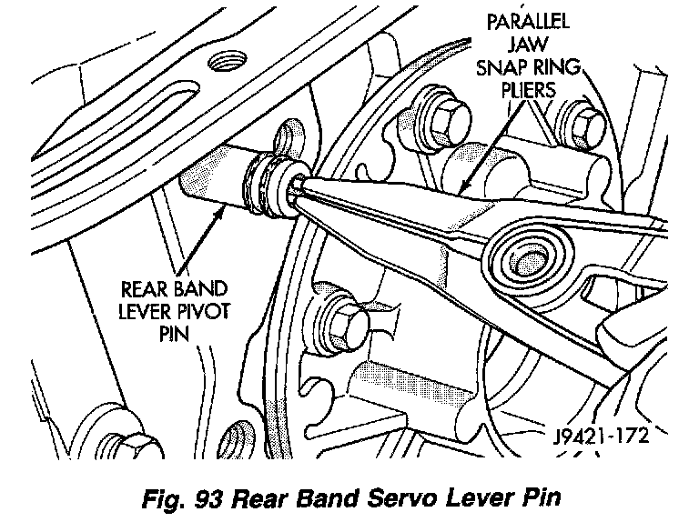
d. Using snap-ring plier, pull rear band lever pivot from transmission case.
e. Separate rear band servo lever from transmission.
Fig. 94:
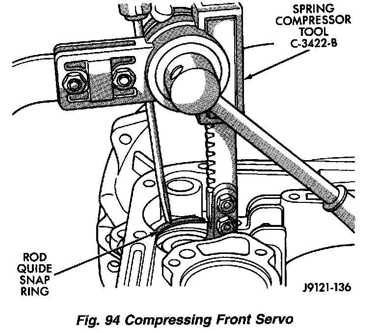
34. Compress front servo rod guide about 1/8 inch with large C-clamp and Tool C-4470, or Spring Compressor Tool C-3422-B.
35. Remove front servo rod guide snap ring. Exercise caution when removing snap ring. Servo bore can be scratched or nicked if care is not exercised.
36. Remove compressor tools and remove front servo rod guide, spring and servo piston.
Fig. 95:
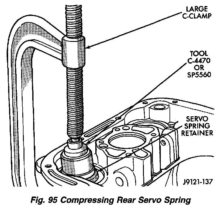
37. Compress rear servo spring retainer about 1/16 inch with C-clamp and Tool C-4470 or SP-5560. Valve Spring Compressor C-3422-B can also be used to compress spring retainer.
38. Remove rear servo spring retainer snap ring. Then remove compressor tools and remove rear servo spring and piston.
ASSEMBLY
1. Install rear servo piston, spring and spring retainer. Compress rear servo spring and retainer with Compressor Tool C-3422-B or a large C-clamp.
2. Install front servo piston, spring, and rod guide. Compress front servo rod guide with Valve Spring Compressor C-3422-B and install servo snap ring.
3. Assemble link bar to band. Notched side of link toward band.
4. Insert rear band through pan opening in transmission case.
5. Insert hook on band onto adjuster lever.
6. Align holes in link bar with hole in transmission case outboard of rear support opening.
7. Insert anchor pin into case through link bar.
Fig. 96:
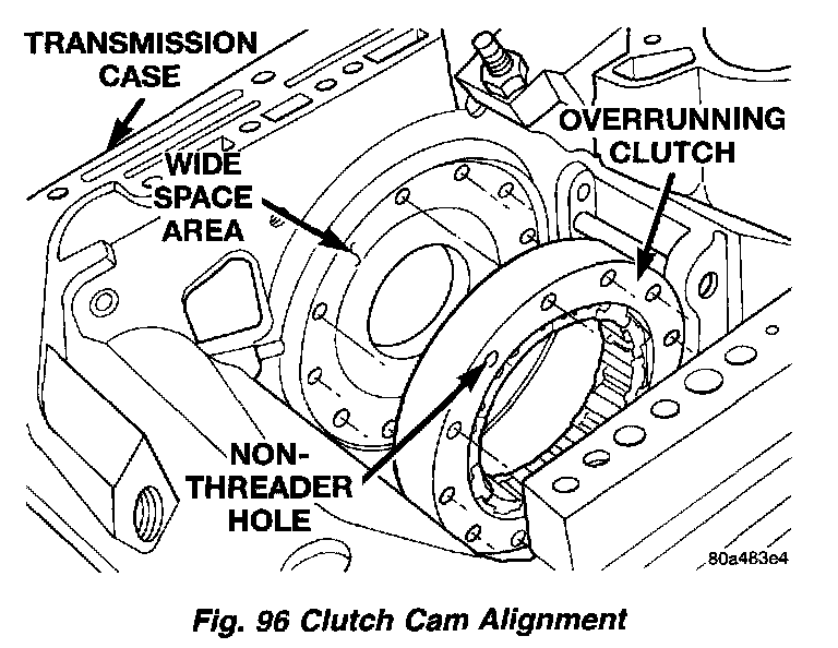
8. Examine bolt holes in overrunning clutch cam. Note that one hole is not threaded. This hole must align with blank area in clutch cam bolt circle.
NOTE: The bolt holes in cam are slightly countersunk on one side. This side of cam faces rearward (toward rear support).
9. Lubricate overrunning clutch rollers, springs and cam with MOPAR ATF+4, type 9602, transmission fluid.
10. Position overrunning clutch on a clean, flat work surface with countersunk holes downward.
11. Place rear of low-reverse drum over overrunning clutch and align clutch rollers to hub of drum.
12. While slightly pivoting low-reverse drum, push hub of drum into overrunning clutch. Verify that countersunk holes are facing outward. Cam should be able to rotate in the drum clockwise only.
13. Insert a suitable awl through the rear support mounting hole closest to the pan sealing face. The awl should be next to the wide space area at the back of transmission case.
14. Insert low-reverse drum and overrunning clutch into front of transmission case and into rear band.
15. Insert awl tip into the threaded hole next to the non-threaded hole in the overrunning clutch cam. Verify that non-threaded hole is aligned with wide space area on transmission case.
16. Push low-reverse drum rearward to close gap between cam and case.
17. Install overrunning clutch cam bolts. Clutch cam bolts are shorter than rear support bolts. Tighten cam bolts to 17 Nm (150 inch lbs. or 13 ft. lbs.) torque.
18. Hold low-reverse drum in position so rear support will not push it out of overrunning clutch.
Fig. 97:
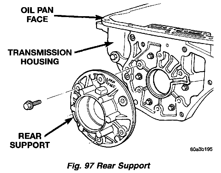
19. Insert rear support into opening at rear of transmission case.
20. Align support with the embossed arrow in the direction of the pan face.
21. Install and tighten rear support bolts to 17 Nm (150 inch lbs.) torque.
Fig. 98:
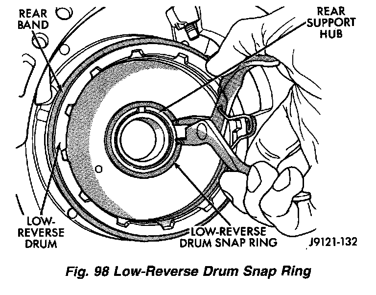
22. Install snap ring to retain low-reverse drum to hub of rear support.
23. Lubricate output shaft, rear support bore and low-reverse drum hub with transmission fluid.
Fig. 99:
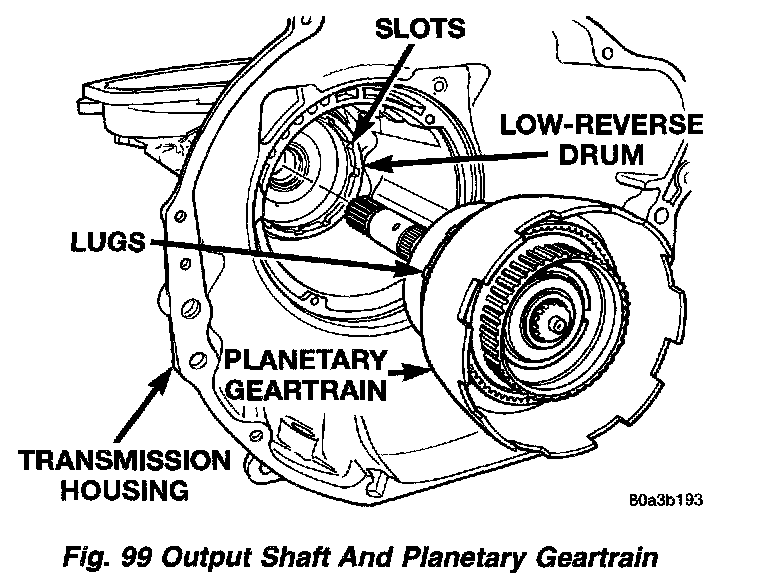
24. Install assembled output shaft and planetary gear-train in case.
25. Align drive lugs on rear planetary gear with slots in low-reverse drum. Then seat planetary assembly in drum.
26. Install governor on output shaft.
27. Turn and secure transmission so that front opening is upward.
28. Assemble front and rear clutches together.
Fig. 100:
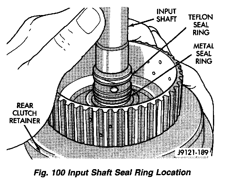
a. Check input shaft seal rings. Verify that diagonal-cut ends of Teflon seal ring are properly joined and ends of metal ring are correctly hooked together. Also be sure rings are installed in sequence shown.
b. Align teeth on clutch discs in line.
Fig. 101:
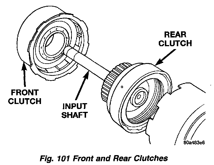
c. Insert input shaft on rear clutch into center of front clutch.
Fig. 103:
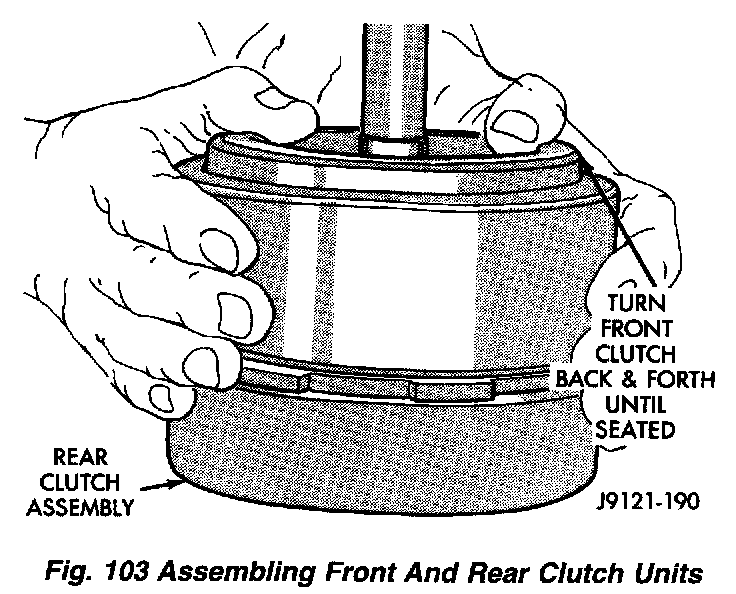
d. Engage teeth on rear clutch hub into teeth on clutch. Rotate front clutch retainer back and forth until completely seated on rear clutch.
Fig. 102:
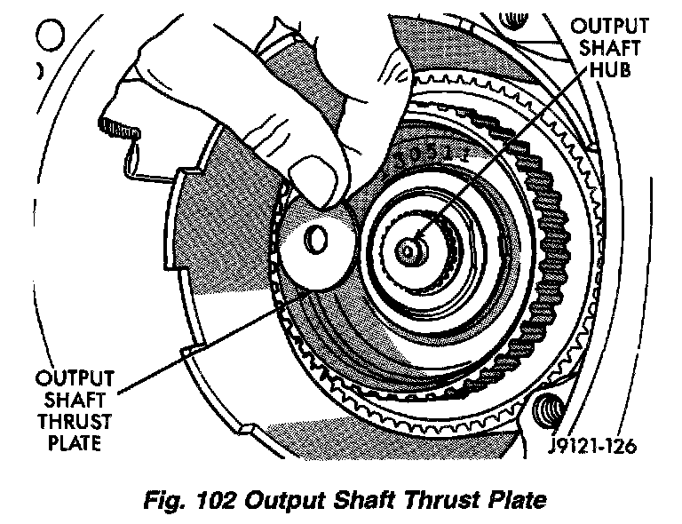
29. Install output shaft thrust plate on shaft hub in planetary gear-train driving shell. Use petroleum jelly to hold thrust plate in place.
30. Check rear clutch thrust washer. Use additional petroleum jelly to hold washer in place if necessary.
Fig. 104:
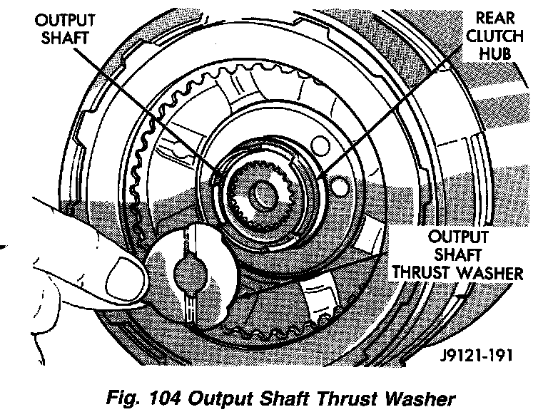
31. Coat output shaft thrust washer with petroleum jelly. Install washer in rear clutch hub. Use enough petroleum jelly to hold washer in place. Be sure grooved side of washer faces rearward (toward output shaft) as shown. Also note that washer only fits one way in clutch hub.
Fig. 105:
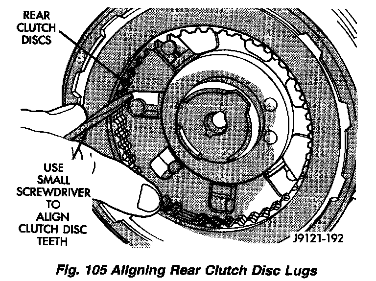
32. Align drive teeth on rear clutch discs with small screwdriver. This will make installation into front of planetary gear-train easier.
Fig. 106:
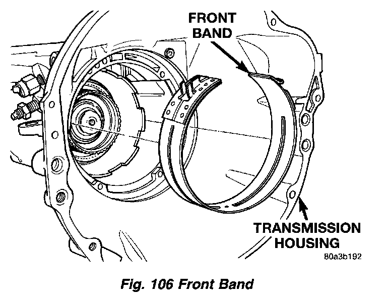
33. Insert front band into opening at front of transmission case.
Fig. 107:
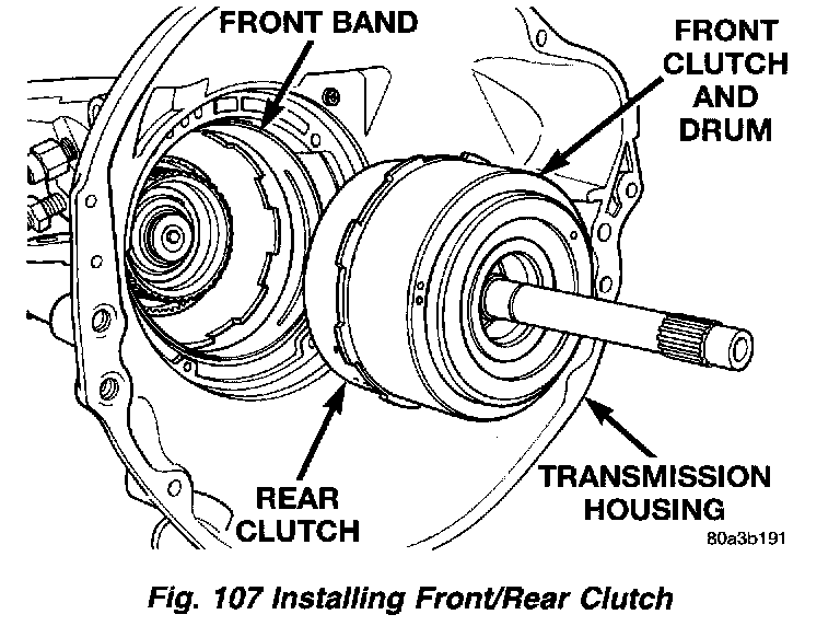
34. Install front and rear clutch units as assembly. Align rear clutch with front annulus gear and install assembly in driving shell. Be sure output shaft thrust washer and thrust plate are not displaced during installation.
36. Carefully work assembled clutches back and forth to engage and seat rear clutch discs on front annulus gear. Verify that front clutch drive lugs are fully engaged in slots of driving shell after installation.
36. Engage front band on adjusting screw and hold band in place.
Fig. 108:
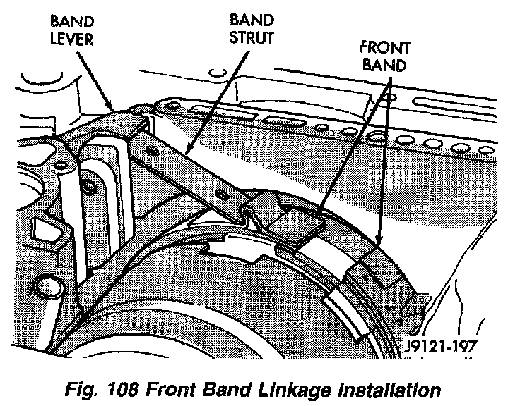
37. Install strut between band lever and front band.
38. Tighten front band adjusting screw until band just grips clutch retainer. Verify that front/rear clutches are still seated before continuing.
Fig. 109:
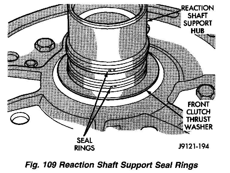
39. Verify that reaction shaft support hub seal rings are hooked together.
Fig. 110:
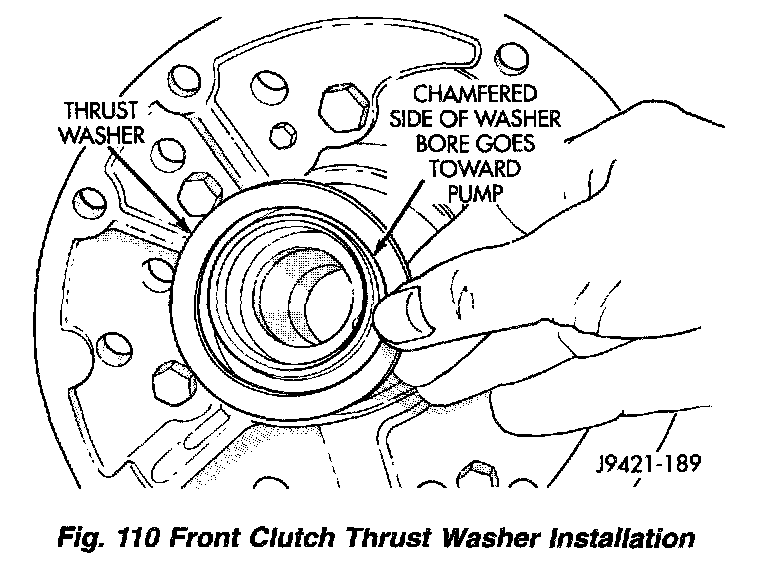
40. Coat front clutch thrust washer with petroleum jelly to hold it in place. Then install washer over reaction shaft hub and seat it on pump.
CAUTION: The thrust washer bore (I.D.), is chamfered on one side. Make sure the chamfered side is installed so it faces the pump.
Fig. 111:
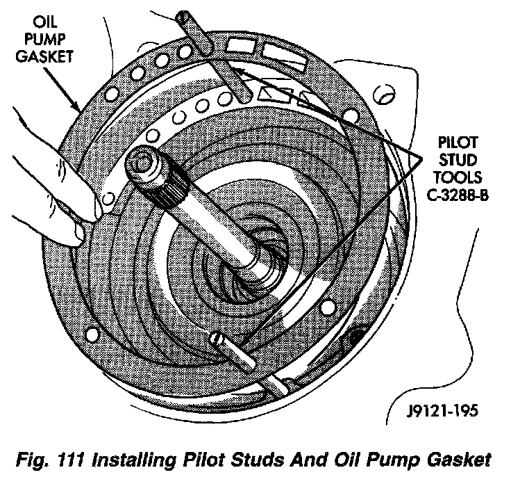
41. Thread two Pilot Stud Tools C-3288-B into bolt holes in oil pump flange.
42. Align and install oil pump gasket.
43. Lubricate oil pump seals with MOPAR Door Ease, or Ru-Glyde, Door Eze, or ATF+4.
Fig. 112:
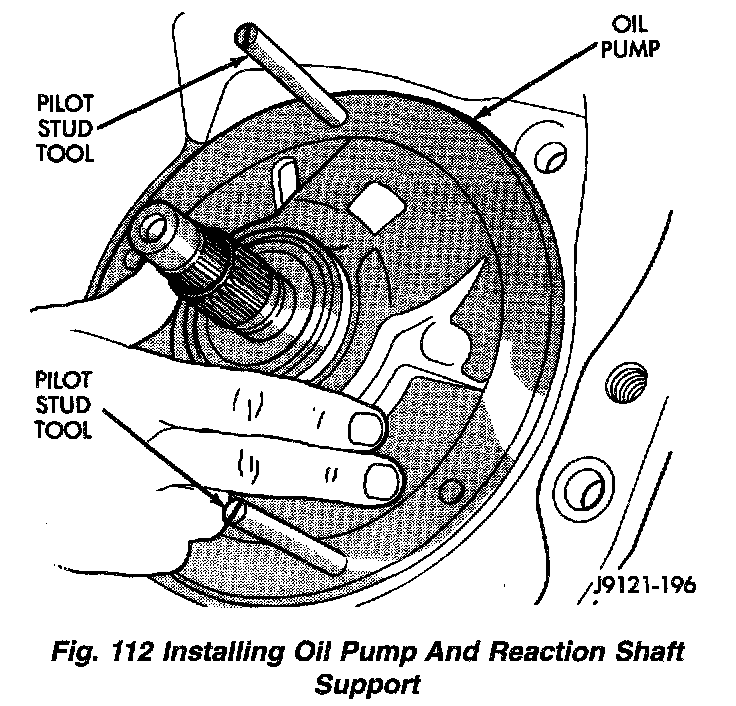
44. Install oil pump. Align and position pump on pilot studs. Slide pump down studs and work it into front clutch hub and case by hand. Then install two or three pump bolts to hold pump in place.
45. Remove pilot stud tools and install remaining oil pump bolts. Tighten bolts alternately in diagonal pattern to 20 Nm (15 ft. lbs.).
Fig. 113:
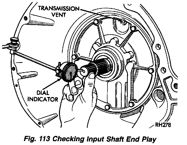
46. Measure input shaft end play.
NOTE: If end play is incorrect, transmission is incorrectly assembled, or output shaft thrust washer and/or thrust plate are worn and need to be changed.
a. Attach dial indicator (C-3339) to converter housing. Position indicator plunger against input shaft and zero indicator.
b. Move input shaft in and out and record reading. End play should be 0.56 - 2.31 mm (0.022 - 0.91 inch).
47. Position transmission on work surface with pan face upward.
48. Install valve body.
49. Adjust front and rear bands.
50. Install fluid filter and pan.
51. Install rear extension housing.
52. Install torque converter.