Housing Assembly HVAC: Service and Repair
The heater-A/C housing assembly must be removed from the vehicle and the two halves of the housing separated for service access of the heater core, evaporator coil, blend-air door(s), and each of the various mode control doors.WARNING: ON VEHICLES EQUIPPED WITH AIRBAGS, REFER TO AIRBAGS SYSTEMS BEFORE ATTEMPTING ANY STEERING WHEEL, STEERING COLUMN, OR INSTRUMENT PANEL COMPONENT DIAGNOSIS OR SERVICE. FAILURE TO TAKE THE PROPER PRECAUTIONS COULD RESULT IN ACCIDENTAL AIR-BAG DEPLOYMENT AND POSSIBLE PERSONAL INJURY.
REMOVAL
1. Disconnect and isolate the battery negative cable.
2. Remove the instrument panel from the vehicle. For these procedures, refer to Body and Frame/ Interior trim/ Dashboard/Instrument Panel/ Service and Repair/ Procedures. Service and Repair
3. Recover the refrigerant from the refrigerant system. Refer to: "Heating and Air Conditioning : Service and Repair" Service and Repair
4. Disconnect the liquid line refrigerant line from the evaporator inlet tube. Install plugs in, or tape over all of the opened refrigerant line fittings.
5. Disconnect the suction line refrigerant line from the evaporator outlet tube. Install plugs in, or tape over all of the opened refrigerant line fittings.
6. Disconnect the heater hoses from the heater core tubes. Clamp off the heater hoses to prevent loss of coolant. Install plugs in, or tape over the opened heater core tubes.
7. If the vehicle is equipped with the manual temperature control system, unplug the heater-A/C system vacuum supply line connector from the tee fitting near the heater core tubes. Refer to Heating and Air Conditioning/ Control Assembly, HVAC/ Service and Repair/ Procedures. Service and Repair
8. Remove the coolant reserve/overflow bottle from the passenger side inner fender shield. Refer to Engine, Cooling and Exhaust/ Cooling System/ Coolant Reservoir/ Description and Operation. Description and Operation
9. Remove the Powertrain Control Module (PCM) from the passenger side dash panel in the engine compartment and set it aside. Do not unplug the PCM wire harness connectors. Service and Repair
Heater-A/C Housing Remove/Install:
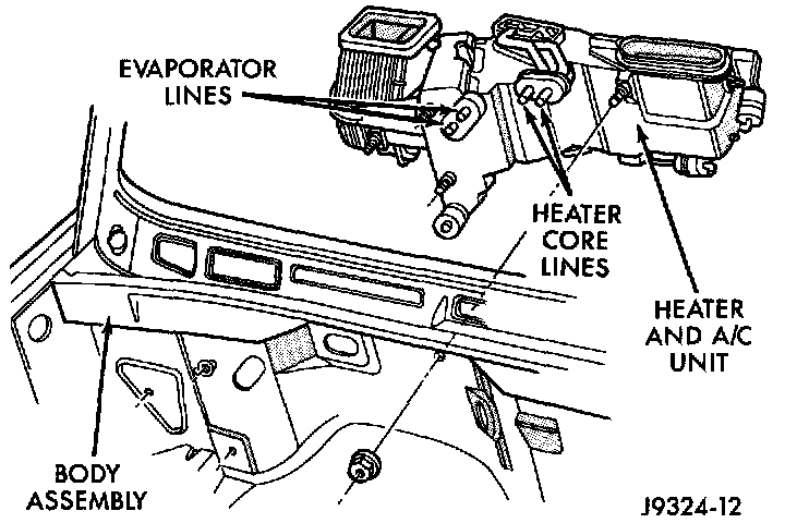
10. Remove the nuts from the heater-A/C housing mounting studs on the engine compartment side of the dash panel.
Rear Floor Heat Ducts:
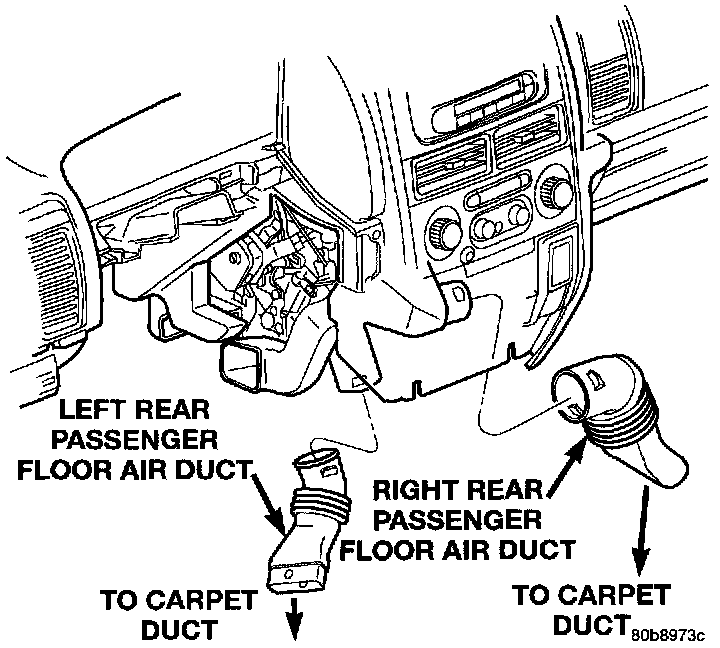
11. Remove the rear floor heat ducts from the floor heat duct outlets.
12. Unplug the heater-A/C housing wire harness connectors.
Heater A/C Housing Remove/Install:
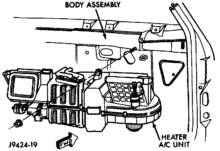
13. Remove the heater-A/C housing mounting nuts from the studs on the passenger compartment side of the dash panel.
14. Remove the heater-A/C housing from the vehicle, ensuring that the interior is covered in case of loss of fluids.
INSTALLATION
1. Position the heater-A/C housing to the dash panel. Be certain that the evaporator condensate drain tube and the housing mounting studs are inserted into their correct mounting holes. Service and Repair
2. Install the heater-A/C housing mounting nuts to the studs on the passenger compartment side of the dash panel. Tighten the nuts to 4.5 Nm (40 in. lbs.). Service and Repair
3. Connect the heater-A/C housing wire harness connectors. Service and Repair
4. Reinstall the rear floor heat ducts to the center floor heat duct outlets.
5. Install and tighten the nuts onto the heater A/C housing mounting studs on the engine compartment side of the dash panel. Tighten the nuts to 7 Nm (60 in. lbs.).
6. Reinstall the PCM to the passenger side dash panel in the engine compartment. Service and Repair
7. Reinstall the coolant reserve/overflow bottle to the passenger side inner fender shield.
8. If the vehicle is equipped with the manual temperature control system, connect the heater-A/C system vacuum supply line connector to the tee fitting near the heater core tubes. Service and Repair
9. Unclamp/unplug the heater core hoses and tubes. Connect the heater hoses to the heater core tubes and fill the engine cooling system.
10. Unplug or remove the tape from the suction line and the evaporator outlet tube fittings. Connect the suction line coupler to the evaporator outlet tube. Service and Repair
11. Unplug or remove the tape from the liquid line and the evaporator inlet tube fittings. Connect the liquid line coupler to the evaporator inlet tube.
12. Evacuate the refrigerant system. Service and Repair
13. Charge the refrigerant system. Service and Repair
14. Install the instrument panel in the vehicle. For these procedures, refer to Body and Frame/ Interior trim/ Dashboard/Instrument Panel/ Service and Repair/ Procedures. Service and Repair
15. Connect the battery negative cable.
16. Start the engine and check for proper operation of the heating and air conditioning systems.