Multi-Function Switch Mounting Housing
REMOVALWARNING: ON VEHICLES EQUIPPED WITH AIRBAGS, DISABLE THE AIRBAG SYSTEM BEFORE ATTEMPTING ANY STEERING WHEEL, STEERING COLUMN, OR INSTRUMENT PANEL COMPONENT DIAGNOSIS OR SERVICE. DISCONNECT AND ISOLATE THE BATTERY NEGATIVE (GROUND) CABLE, THEN WAIT TWO MINUTES FOR THE AIRBAG SYSTEM CAPACITOR TO DISCHARGE BEFORE PERFORMING FURTHER DIAGNOSIS OR SERVICE. THIS IS THE ONLY SURE WAY TO DISABLE THE AIRBAG SYSTEM. FAILURE TO TAKE THE PROPER PRECAUTIONS COULD RESULT IN ACCIDENTAL AIRBAG DEPLOYMENT AND POSSIBLE PERSONAL INJURY.
NOTE: Before starting this procedure, be certain to turn the steering wheel until the front wheels are in the straight-ahead position.
1. Place the front wheels in the straight-ahead position.
2. Disconnect and isolate the battery negative cable.
3. Remove the clockspring from the multi-function switch mounting housing. (Refer to CLOCKSPRING - REMOVAL).
4. Remove the left multi-function switch from the multi-function switch mounting housing. (Refer to LEFT MULTI-FUNCTION SWITCH - REMOVAL - LEFT MULTI-FUNCTION SWITCH).
5. Remove the right multi-function switch from the multi-function switch mounting housing. (Refer to RIGHT MULTI-FUNCTION SWITCH - REMOVAL).
Fig.27 Multi-Function Switch Mounting Housing Screw Remove/Install:
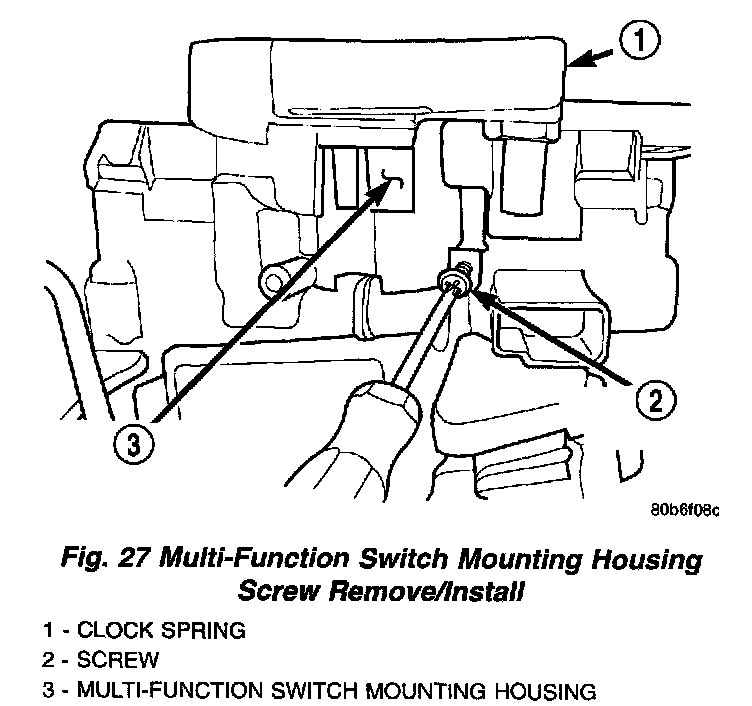
6. From the underside of the steering column, remove the one screw that secures the multi-function switch mounting housing to the steering column housing.
Fig.28 Multi-Function Switch Mounting Housing Remove/Install:
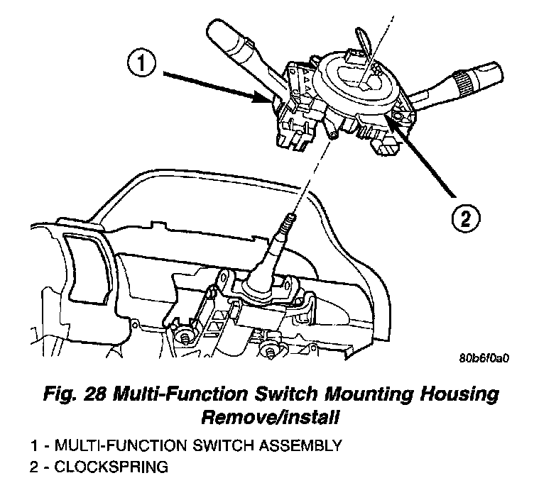
7. Remove the multi-function switch mounting housing from the top of the steering column.
INSTALLATION
WARNING: ON VEHICLES EQUIPPED WITH AIRBAGS, DISABLE THE AIRBAG SYSTEM BEFORE ATTEMPTING ANY STEERING WHEEL, STEERING COLUMN, OR INSTRUMENT PANEL COMPONENT DIAGNOSIS OR SERVICE. DISCONNECT AND ISOLATE THE BATTERY NEGATIVE (GROUND) CABLE, THEN WAIT TWO MINUTES FOR THE AIRBAG SYSTEM CAPACITOR TO DISCHARGE BEFORE PERFORMING FURTHER DIAGNOSIS OR SERVICE. THIS IS THE ONLY SURE WAY TO DISABLE THE AIRBAG SYSTEM. FAILURE TO TAKE THE PROPER PRECAUTIONS COULD RESULT IN ACCIDENTAL AIRBAG DEPLOYMENT AND POSSIBLE PERSONAL INJURY.
NOTE: Before starting this procedure, be certain that the front wheels are still in the straight-ahead position.
Fig.31 Turn Signal Cancel Cam Alignment:
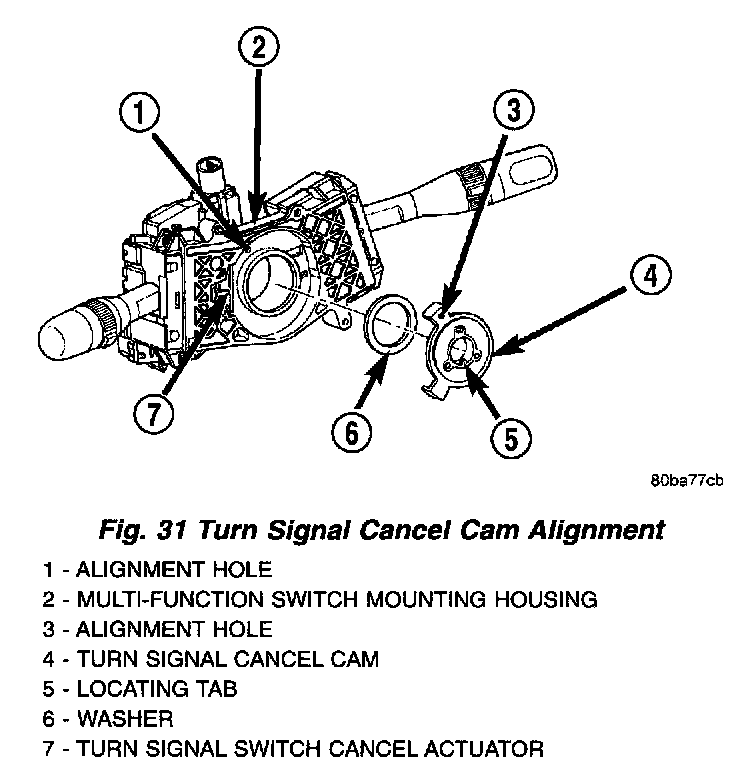
1. Rotate the turn signal cancel cam in the multi-function switch mounting housing until the alignment hole in the one cam lobe is aligned with the alignment hole in the back of the housing. The oblong hole in the hub of the cam should now be at the top, and the locating tab in the hub of the cam should be at the bottom.
2. Position the multi-function switch mounting housing onto the top of the steering column. The locating tab in the hub of the turn signal cancel cam must be engaged with the alignment groove in the bottom of the upper steering column shaft.
Fig.32 Multi-Function Switch Mounting Housing Screw Remove/Install:

3. From the underside of the steering column, install and tighten the one screw that secures the multi-function switch mounting housing to the top of the column housing. Tighten the screw to 1.9 Nm (17 in. lbs.).
4. Reinstall the right multi-function switch onto the multi-function switch mounting housing. (Refer to RIGHT MULTI-FUNCTION SWITCH - INSTALLATION).
5. Reinstall the left multi-function switch onto the multi-function switch mounting housing. (Refer to LEFT MULTI-FUNCTION SWITCH - INSTALLATION - LEFT MULTI-FUNCTION SWITCH).
6. Reinstall the clockspring onto the multi-function switch mounting housing. (Refer to CLOCKSPRING - INSTALLATION).
7. Reconnect the battery negative cable.