Battery Holddown
REMOVALAll of the battery hold down hardware can be serviced without removal of the battery or the battery tray and support unit.
1. Turn the ignition switch to the OFF position. Be certain that all electrical accessories are turned OFF.
2. Loosen the battery negative cable terminal clamp pinch-bolt hex nut.
3. Disconnect the battery negative cable terminal clamp from the battery negative terminal post. If necessary use a battery terminal puller to remove the terminal clamp from the battery post.
Fig.16 Battery Hold Downs Remove/Install:
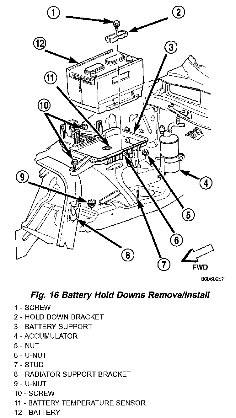
4. Remove the screw with washer that secures the battery hold down bracket to the U-nut on the inboard side of the battery tray and support unit (Fig. 16).
5. Remove the battery hold down bracket from the battery tray and support unit.
INSTALLATION
All of the battery hold down hardware can be serviced without removal of the battery or the battery tray and support unit.
1. Clean and inspect the battery hold down hardware. Refer to the procedures in this section.
2. Be certain that the battery is properly positioned in the battery tray and support unit. The ledge on the outboard side of the battery case must be engaged under the lip on the outboard side of the battery tray and support unit.
3. Position the battery hold down bracket over the ledge on the inboard side of the battery case in the battery tray and support unit. Be certain that the ledge on the bottom of the hold down bracket is oriented towards the inboard side of the battery case. Proper hold down bracket orientation may also be determined by noting the direction of the arrow-like formations of the molded reinforcing ribs on the top of the hold down bracket. These arrows should be pointed towards the battery
4. Install and tighten the screw that secures the battery hold down bracket to the U-nut on the inboard side of the battery tray and support unit. Tighten thew screw to 3.4 Nm (30 in. lbs.).
5. Reconnect the battery negative cable terminal clamp to the battery negative terminal post. Tighten the terminal clamp pinch-bolt hex nut to 8.4 Nm (75 in. lbs.).