Alarm System - False Alarms
NUMBER: 08-015-03GROUP: Electrical
DATE: Jun. 06, 2003
THIS BULLETIN IS BEING PROVIDED IN ADVANCE. DO NOT ORDER PARTS OR PERFORM ANY ACTIONS RELATED TO THIS BULLETIN UNTIL JULY 11, 2003.
SUBJECT:
The Intrusion Alarm When In Its Armed Mode May Cause A False Alarm
OVERVIEW:
This bulletin involves installing additional support for the intrusion alarm module by adding either blocks of foam or a support bracket.
MODELS:
2002 - 2003 (WG) Grand Cherokee (International Markets)
NOTE:
THIS BULLETIN APPLIES TO VEHICLES EQUIPPED WITH A PREMIUM VEHICLE SECURITY SYSTEM (SALES CODE = LSC).
SYMPTOM/CONDITION:
The customer may state that when the vehicle alarm system is armed (enabled) the siren will activate for no known reason. This condition may be caused by an intrusion alarm module that is too sensitive to certain externally generated vibrations.
DIAGNOSIS:
If the customer has experienced the above condition perform the Repair Procedure.
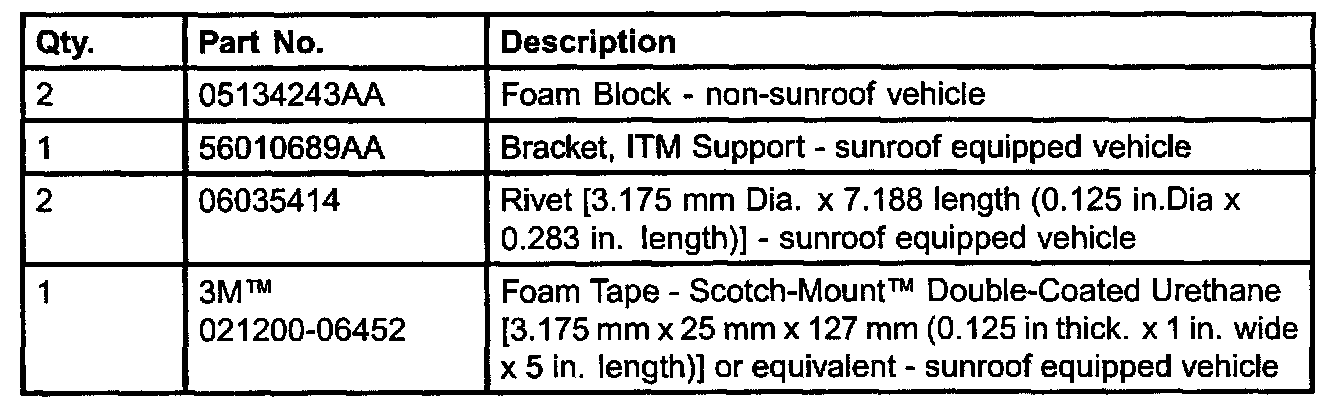
PARTS REQUIRED

EQUIPMENT REQUIRED
REPAIR PROCEDURE:
IF VEHICLE DOES NOT HAVE A SUNROOF:
1. Turn the ignition switch to the OFF position.
2. Disconnect the negative battery cable from the negative battery terminal.
3. Remove the Intrusion Alarm Module (ITM) from the plastic ITM snap ring by depressing the two locking tabs. The locking tabs can be accessed with a thin blade screw driver through the two small slots on the rear facing side of the ITM. The ITM snap ring remains attached to the headliner.
4. Remove the electrical harness connector from the ITM.
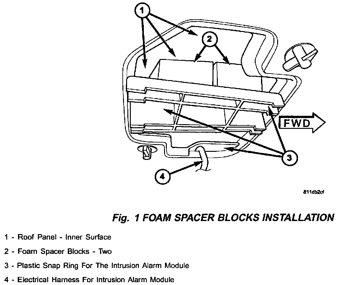
5. While pulling down on the ITM snap ring, install two foam blocks to the top side of the ITM snap ring. The foam blocks should adhere to the ITM snap ring and be positioned so that they are between the snap ring and the roof panel. (Fig. 1)
6. Connect the electrical harness connector to the ITM.
7. Install the ITM to the ITM snap ring.
8. Connect the negative battery cable to the battery negative terminal.
9. Set the clock to the correct time.
IF VEHICLE IS EQUIPPED WITH A SUNROOF:
1. Turn the ignition switch to the OFF position.
2. Disconnect the negative battery cable from the negative battery terminal.
3. Remove the headliner from the vehicle. Refer to the appropriate Grand Cherokee Service Manual for headliner removal and installation procedures.
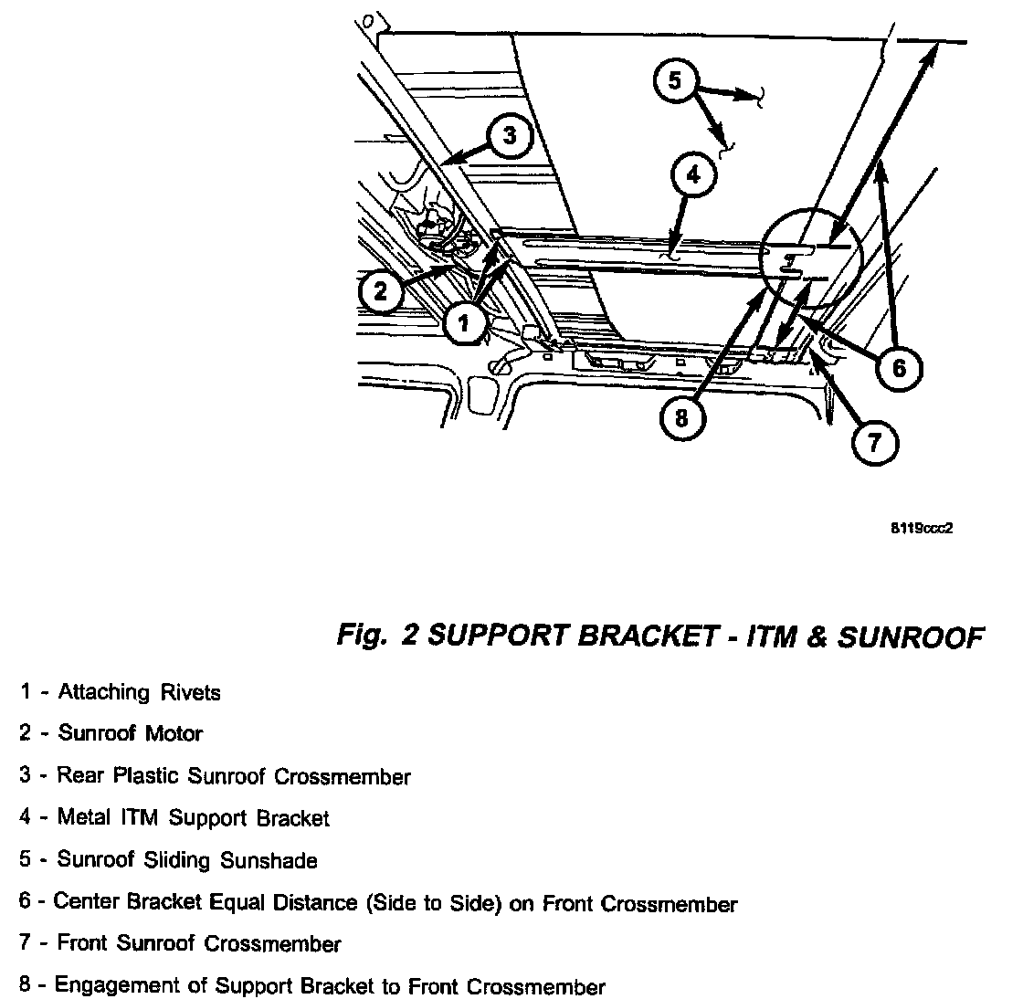
4. Temporarily position the metal ITM support bracket, p/n 56010689AA, between the two sunroof crossmembers. (Fig. 2)
5. Center the ITM support bracket so that it is equal distance from the left and right side of the vehicle. Make alignment marks between the ITM support bracket ends and each sunroof crossmember for later bracket installation.
6. Make certain that the edge of the ITM support bracket is seated to the rear sunroof crossmember.
7. Through the holes at the rear edge of the ITM support bracket, mark each location where two holes will need to be drilled for the attaching rivets.
8. Remove the ITM support bracket.
9. Drill a 3.175 mm (0.125 inch) diameter hole at the two locations that were previously marked on the rear sunroof crossmember. Be careful that the drill bit does not contact the roof panel.
10. Cut two 25 mm (1 inch) long pieces from the original 127 mm (5 inch) long piece of foam tape. The two 25 mm (1 inch) pieces of foam tape will be used to insulate the metal ITM support bracket from the front sunroof crossmember.
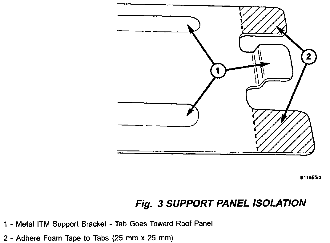
11. Attach a 25 mm (1 inch) piece of foam tape to each metal tab on the ITM support bracket. Once installed the two 25 mm (1 inch) pieces of foam tape should face upward and towards the roof panel. (Fig. 3)
12. Using the previously made alignment marks, carefully install the front edge of the ITM support bracket to the front sunroof crossmember. Make sure both 25 mm (1 inch) pieces of foam tape are adhered to both the support bracket and crossmember.
13. Seat the rear edge of the ITM support bracket to the rear sunroof crossmember. Install both attaching rivets. Make certain the correct length rivet is used or damage to the sunroof sliding sunshade panel may occur.
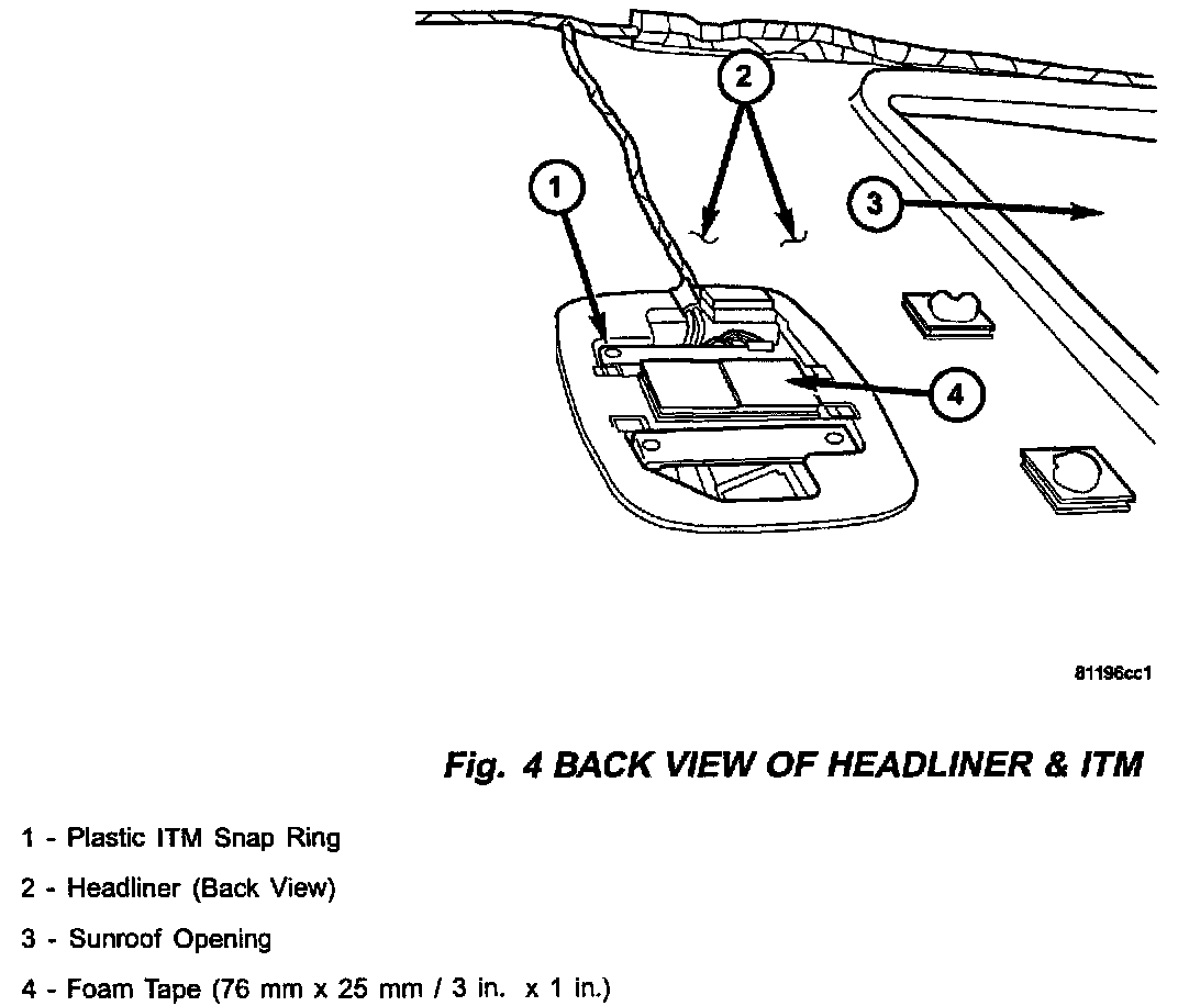
14. Adhere only one side of the remaining 76 mm (3 inch) piece of the foam tape to the center of the ITM snap ring. The tape should be on the side of the snap ring that will face the roof panel and ITM support bracket. Do not remove the remaining protective facing on the foam tape until the headliner has been installed. (Fig. 4)
15. Clean the surface of the ITM support bracket to insure proper adhesion of the foam tape.
16. Install the headliner to the vehicle. Do not install the Intrusion Alarm Module to the ITM snap ring.
17. While pulling down on the ITM snap ring, remove the remaining protective facing on the foam tape. Adhere the foam tape to the ITM support bracket. The ITM snap ring should now be affixed to the new ITM support bracket.
18. Install the Intrusion Alarm Module to the ITM snap ring.
19. Connect the negative battery cable to the battery negative terminal.
20. Set the clock to the correct time.
POLICY:
Reimbursable within the provisions of the warranty.

TIME ALLOWANCE

FAILURE CODE