NV247
REMOVAL1. Shift transfer case into NEUTRAL.
2. Raise vehicle.
3. Remove transfer case drain plug and drain transfer case lubricant.
4. Mark front and rear propeller shaft yokes for alignment reference.
5. Support transmission with jack stand.
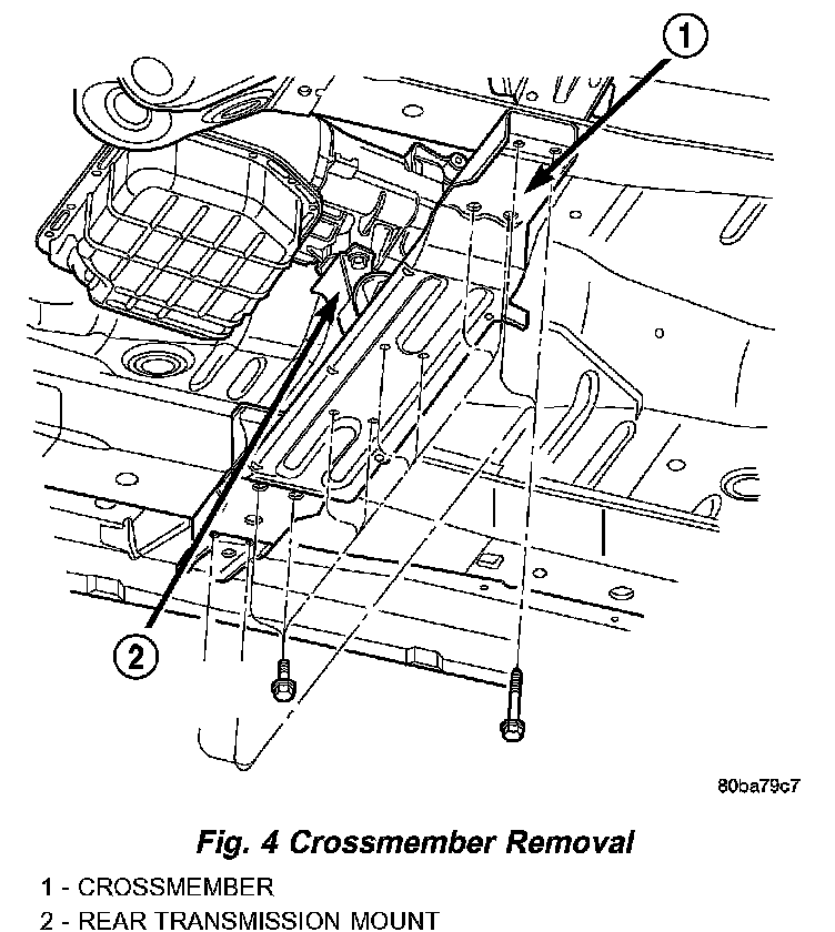
6. Remove rear crossmember and skid plate, if equipped (Fig. 4).
7. Disconnect front propeller shaft from transfer case at companion flange. Remove rear propeller shaft from vehicle.
CAUTION: Do not allow propshafts to hang at attached end. Damage to joint can result.
8. Disconnect transfer case cable from range lever.

9. Disconnect transfer case vent hose (Fig. 5).
10. Support transfer case with transmission jack.
11. Secure transfer case to jack with chains.
12. Remove nuts attaching transfer case to transmission.
13. Pull transfer case and jack rearward to disengage transfer case (Fig. 5).
14. Remove transfer case from under vehicle.
DISASSEMBLY
Position transfer case on shallow drain pan. Remove drain plug and drain lubricant remaining in case.
REAR RETAINER AND OIL PUMP
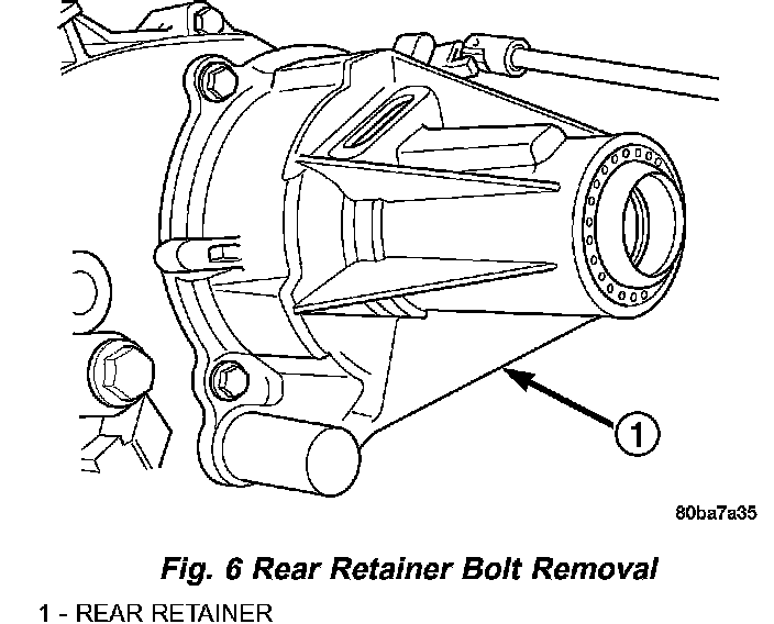
1. Remove rear retainer bolts (Fig. 6).
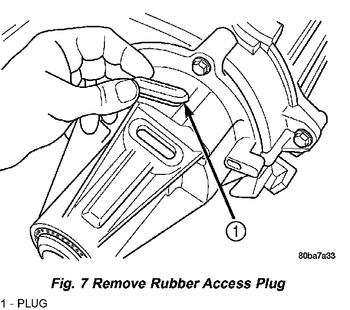
2. Remove rear bearing locating ring access plug (Fig. 7).
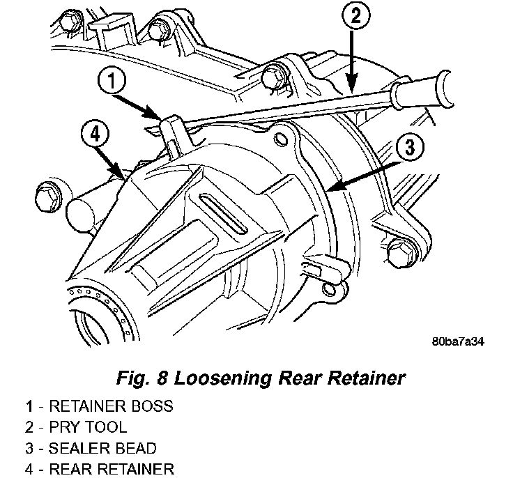
3. Loosen rear retainer with pry tool to break sealer bead. Pry only against retainer boss as shown (Fig. 8).
4. Remove rear retainer as follows:

a. Spread rear bearing locating ring with snap ring pliers (Fig. 9).
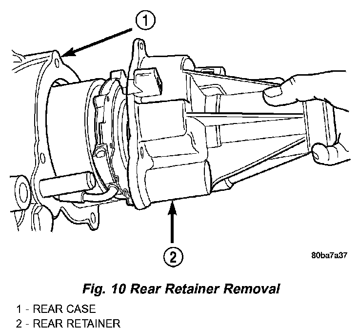
b. Then slide retainer off mainshaft and rear bearing (Fig. 10).
5. Remove rear bearing snap-ring.
6. Remove rear bearing. Note position of bearing locating ring groove for assembly reference.
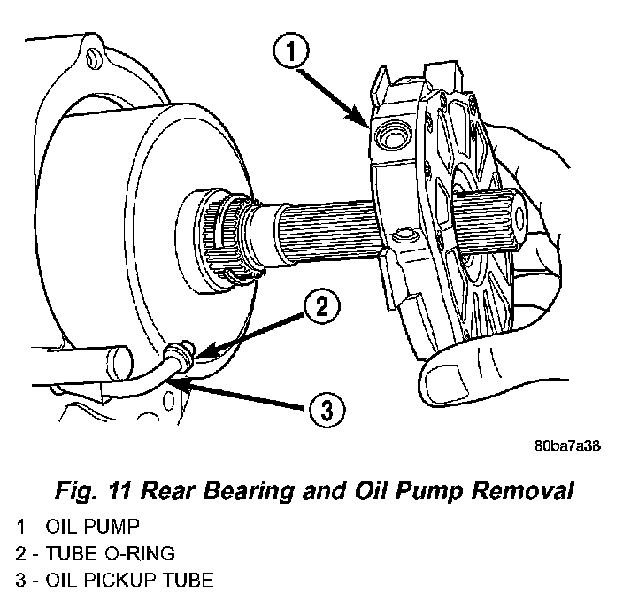
7. Disengage oil pickup tube from oil pump and remove oil pump assembly (Fig. 11).
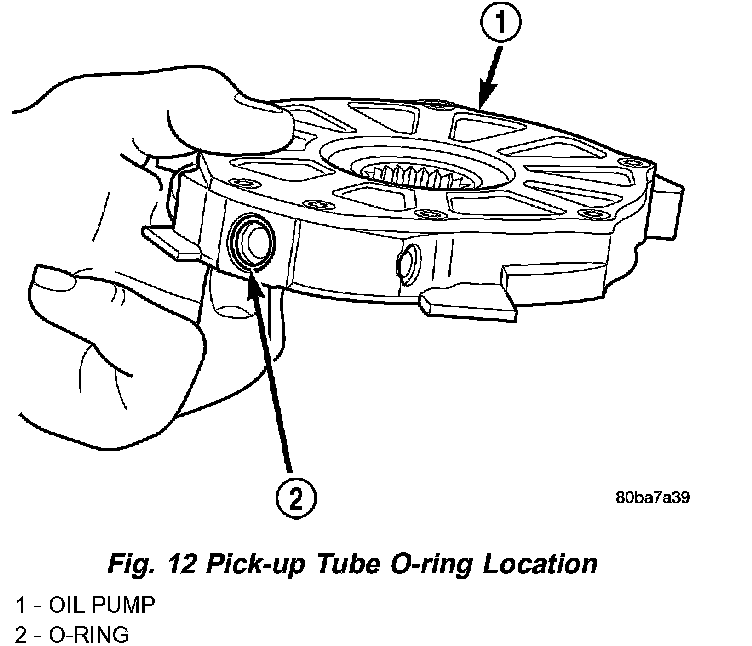
8. Remove pick-up tube O-ring from oil pump (Fig. 12), if necessary. Do not disassemble the oil pump, it is not serviceable.
COMPANION FLANGE AND RANGE LEVER
1. Remove front companion flange nut as follows:
a. Move range lever to 4L position.
b. Remove nut with socket and impact wrench.
2. Remove companion flange. If flange is difficult to remove by hand, remove it with bearing splitter, or with standard two jaw puller. Be sure puller tool is positioned on flange and not on slinger as slinger will be damaged.
3. Remove seal washer from front output shaft. Discard washer as it should not be reused.
4. Remove nut and washer that attach range lever to sector shaft. Then move sector to neutral position and remove range lever from shaft.
NOTE: Note position of range lever so it can be reinstalled correctly.
REAR CASE
1. Support transfer case so rear case is facing upward.
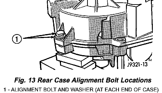
2. Remove bolts holding front case to rear case. The case alignment bolt require flat washers (Fig. 13).
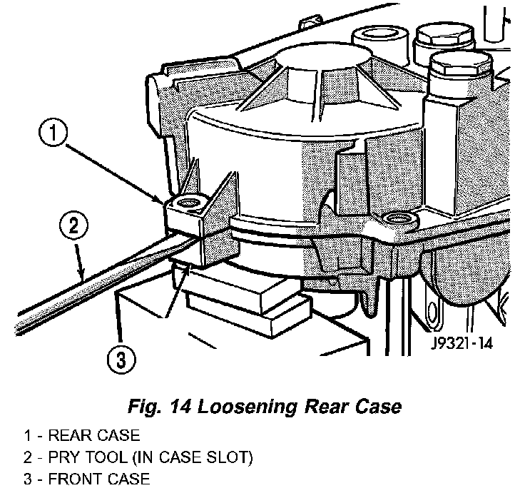
3. Loosen rear case with flat blade screwdriver to break sealer bead. Insert screwdriver blade only into notches provided at each end of case (Fig. 14).
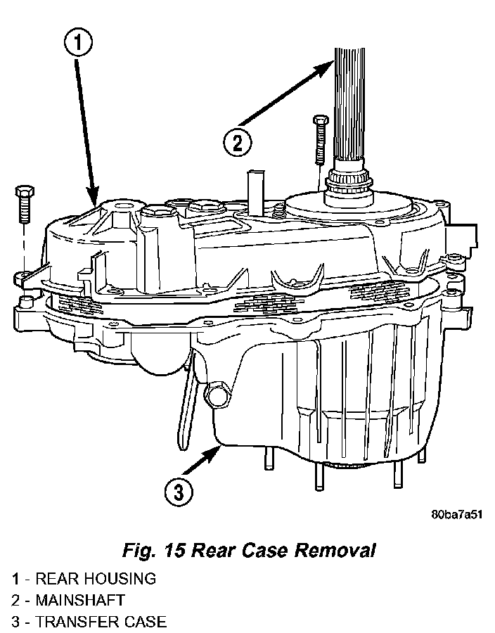
4. Remove rear case (Fig. 15).
PROGRESSIVE COUPLING
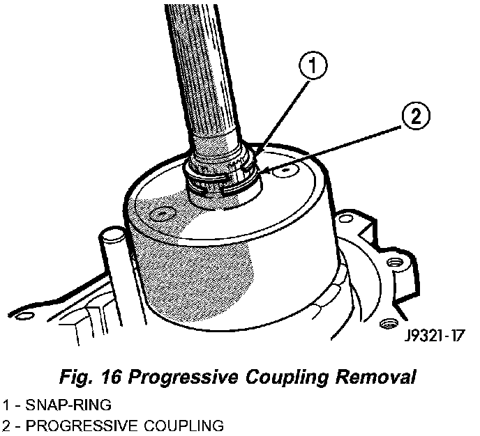
1. Remove oil pump locating snap-ring and progressive coupling thrust washer from the mainshaft (Fig. 16).
2. Remove progressive coupling from mainshaft (Fig. 16).
FRONT OUTPUT SHAFT AND DRIVE CHAIN
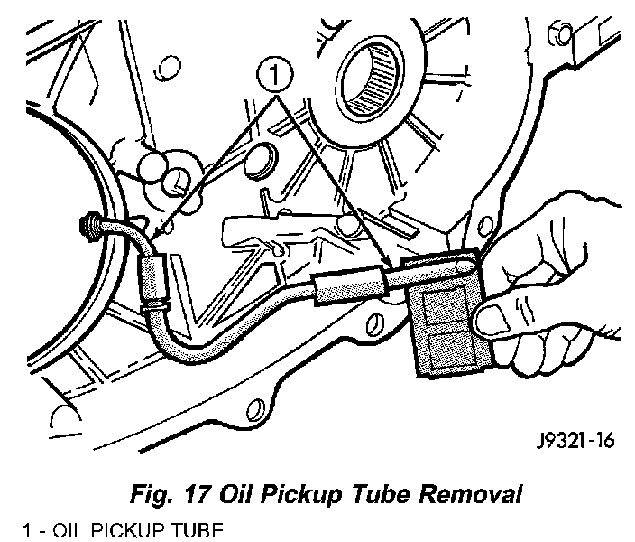
1. Remove oil pickup tube from rear case (Fig. 17).
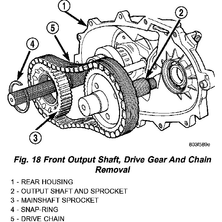
2. Remove drive gear snap-ring (Fig. 18).
3. Disengage drive gear (Fig. 18). Pry gear upward and off mainshaft as shown.
4. Remove front output shaft, drive chain and drive gear as assembly (Fig. 18).
5. Remove output shaft drive gear snap ring.
6. Remove output shaft drive gear from output shaft.
SHIFT FORKS AND MAINSHAFT
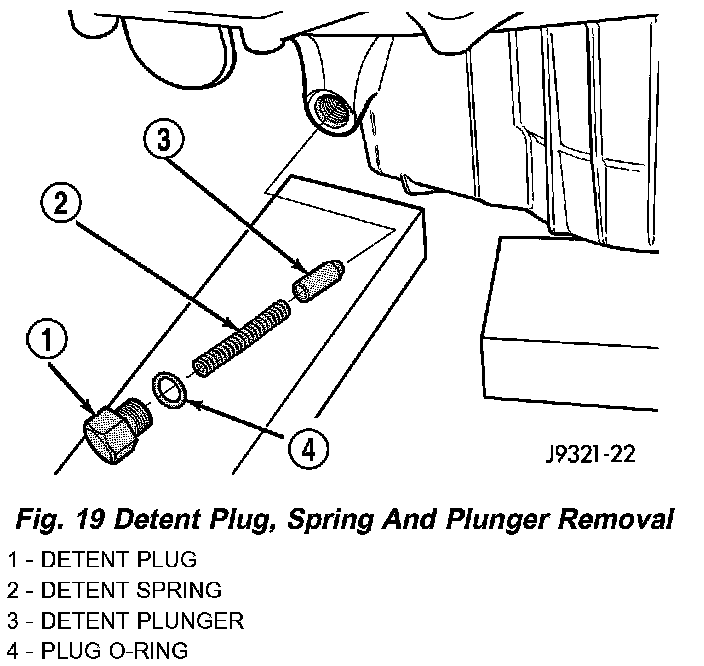
1. Remove detent plug, O-ring, detent spring and detent plunger (Fig. 19).
2. Remove shift rail from shift fork and transfer case housing.
3. Rotate range shift fork until it disengages from shift sector.
4. Remove mainshaft and shift fork from input gear pilot bearing.
NOTE: Loose needle bearings are used to support the drive sprocket hub on the mainshaft. Do not lift mainshaft by drive sprocket hub or needle bearings will become dislodged.
5. Wrap rag around mainshaft underneath drive sprocket hub and remove drive sprocket hub from mainshaft. Be sure to retrieve all the drive sprocket hub needle bearings.
6. Remove snap ring holding clutch sleeve onto mainshaft.
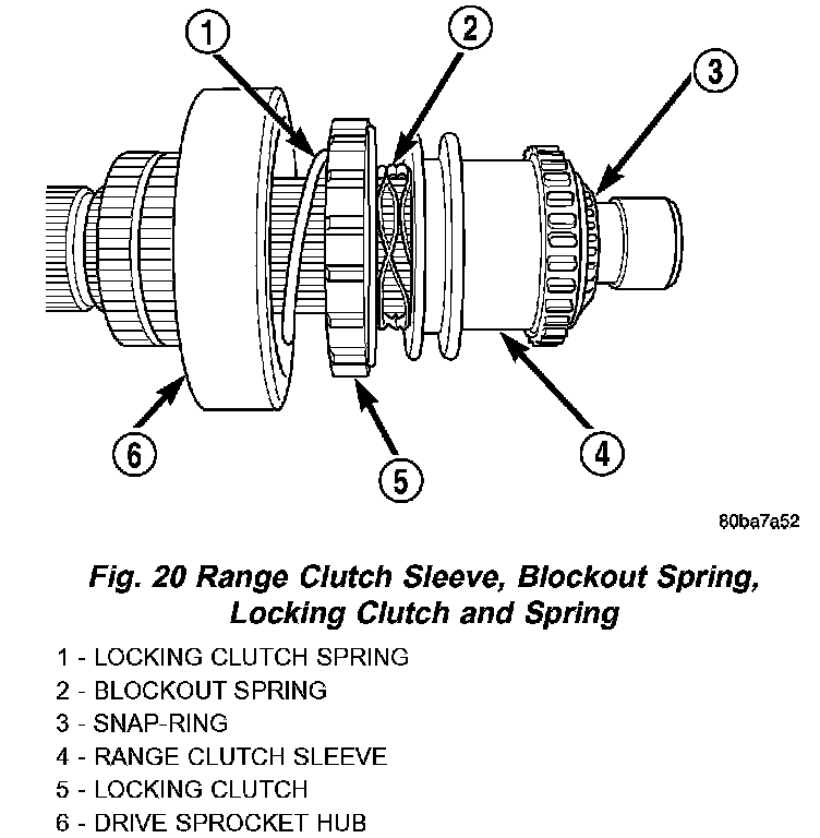
7. Remove range clutch sleeve, blackout spring, locking clutch, and locking clutch spring from mainshaft (Fig. 20).
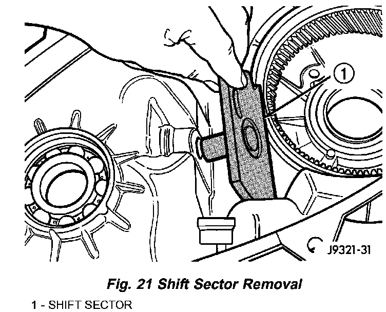
8. Remove shift sector. Rotate and tilt sector as needed to remove it (Fig. 21).
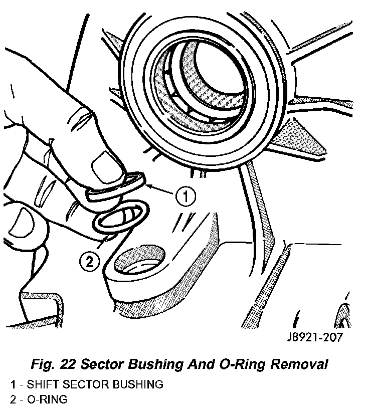
9. Remove shift sector bushing and O-ring (Fig. 22).
INPUT GEAR/LOW RANGE ASSEMBLY
1. Turn front case on side so front bearing retainer is accessible.
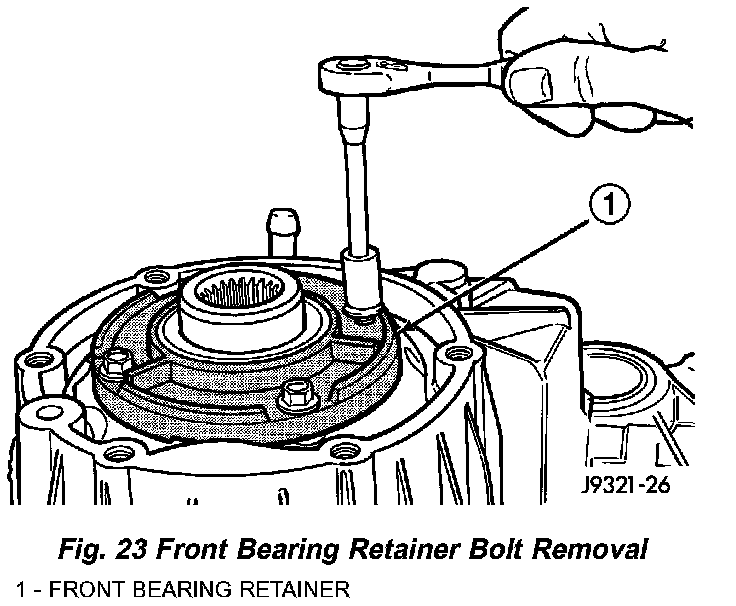
2. Remove front bearing retainer bolts (Fig. 23).
3. Remove front bearing retainer as follows:
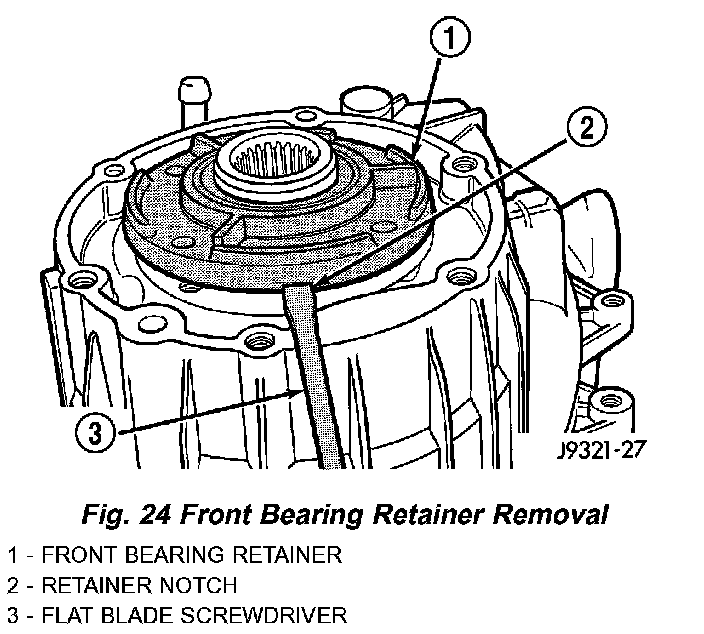
a. Loosen retainer with flat blade screwdriver to break sealer bead. To avoid damaging case and retainer, position screwdriver blade only in slots provided in retainer (Fig. 24).
b. Then remove retainer from case and gear.
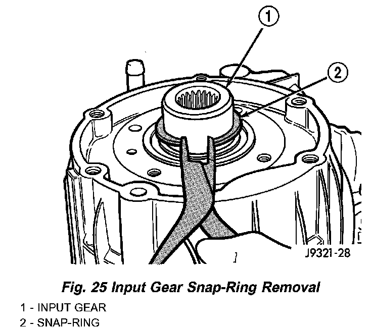
4. Remove snap-ring that retains input gear shaft in front bearing (Fig. 25).
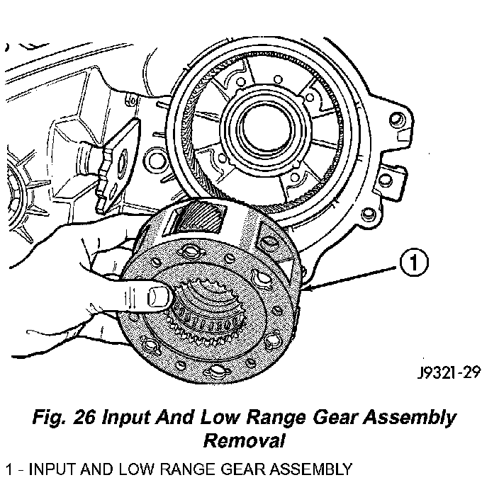
5. Remove input and low range gear assembly (Fig. 26).
6. Remove oil seals from following components:
- front bearing retainer.
- rear retainer.
^ case halves.
INPUT AND LOW RANGE GEAR
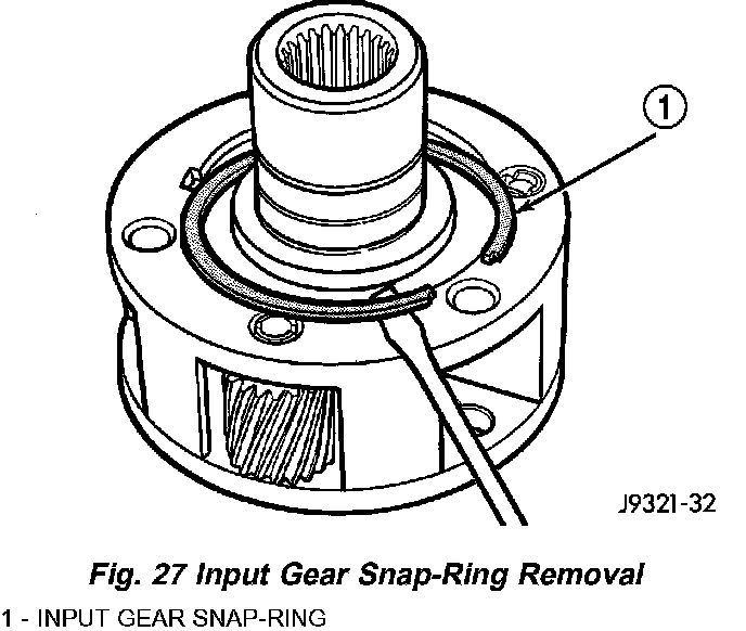
1. Remove snap-ring that retains input gear in low range gear (Fig. 27).

2. Remove retainer (Fig. 28).
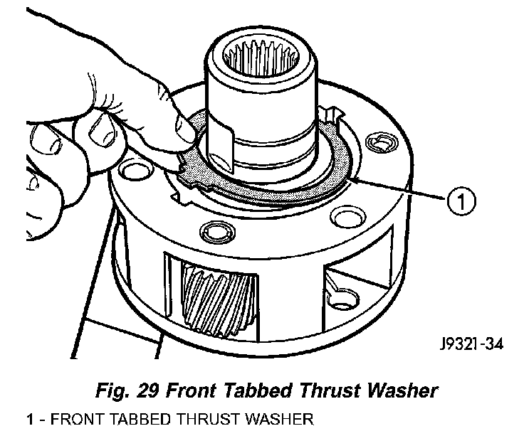
3. Remove front tabbed thrust washer (Fig. 29).
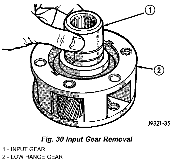
4. Remove input gear (Fig. 30).
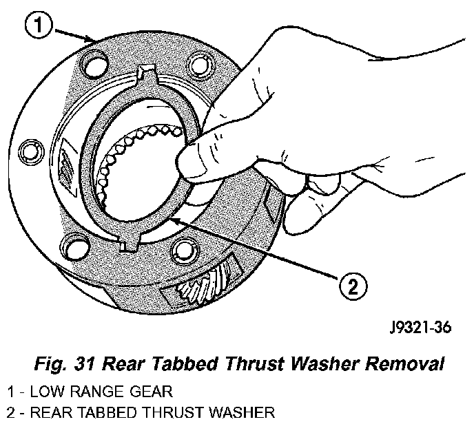
5. Remove rear tabbed thrust washer from low range gear (Fig. 31).
CLEANING
Clean the transfer case components with parts cleaning solvent. Flush the oil passages in the cases and drivetrain components with solvent. This will help remove dirt and particles from these passages.
Dry the transfer case components with compressed air or allow them to air dry on clean shop towels.
Apply compressed air through all oil passages in the cases and gear components to clear them of any residue.
INSPECTION
MAINSHAFT
Examine the mainshaft components carefully for evidence of wear or damage.
Replace the thrust washers if worn or damaged.
Replace the mainshaft and sprocket gears if the teeth or gear bores are worn or damaged.
Replace the mainshaft bearings if worn, flat spotted, brinelled, or damaged in any way.
Replace the mainshaft if it is bent, exhibits wear or damage to the bearing surfaces, splines or gear teeth.
INPUT AND LOW RANGE GEARS
Inspect the low range gear pinions and pinion pins. Replace the low range gear if any of the pins or pinions are worn or damaged.
Inspect the thrust washers, retainer, and snap-ring. Replace the snap-ring if bent, or distorted. Replace the thrust washers and retainer if worn, cracked or damaged in any way.
Examine the input gear carefully. Be sure the gear teeth and bearing surfaces are in good condition. Replace the gear if wear or damage is evident.
Check the input gear pilot bearing. Rotate the bearing and check for roughness or noise. Also check bearing position in the bore. The bearing should be recessed approximately 2.5 mm (0.100 in.) below the top edge of the bore. The bearing should not be seated at the bottom of the bore. Replace the bearing if worn, or roughness is evident. Replace both the gear and bearing if the bearing is a loose fit in the bore.
GEAR CASE AND RETAINERS
Examine both case halves and retainers carefully. Replace any retainer or case half if wear, cracks, or other damage is evident.
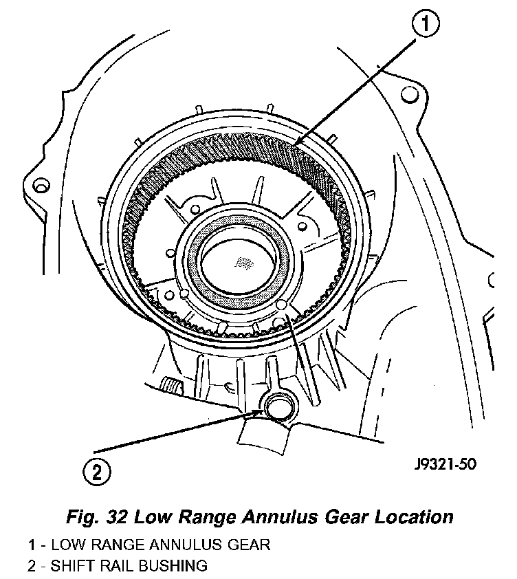
Check condition of the low range annulus gear and the shift rail bushing in the front case (Fig. 32). The low range annulus gear is not a serviceable part. Replace the gear and case as an assembly if the gear is loose, worn, or damaged. The shift rail bushing is a serviceable part and can be replaced if necessary.
Check the bushing in the rear retainer. Replace the bushing if worn or scored.
Examine the sealing surfaces of both case halves and retainers. Small burrs, or scratches on these surfaces can be reduced with crocus cloth or a fine tooth file.
Examine condition of the shift rail bushing in the front case. If the bushing is worn or damaged, it can be removed with a blind hole type puller. A replacement bushing can be installed with a suitable size driver. Recess the bushing slightly below the edge of the bore, but do not seat it all into the case.
GEARTRAIN
Inspect the mainshaft splines, gear teeth and bearing surfaces carefully for evidence of wear, or damage. Replace the shaft if necessary. Do not attempt to salvage it if damaged.
The shift rail and range fork are an assembly. Replace both parts if either is damaged. However, the nylon pads in the fork can be replaced if worn, or cracked.
Inspect the transfer case snap-rings closely. Do not attempt to salvage a distorted snap-ring by straightening or reshaping it. Replace any snap-ring that is distorted, or worn.
Inspect the low range gear, input gear and the gear thrust washers retainer, and snap-ring. The low range gear is serviced as an assembly only. Replace the gear if the case or pinions are damaged.
During inspection, also make sure the seal surface of the input gear is in good condition. Minor nicks on this surface can be reduced with crocus cloth. However, replace the gear if the seal surface is severely scored or worn.
OIL PUMP AND PROGRESSIVE COUPLING
The oil pump and progressive coupling are not serviceable components. Replace the coupling as an assembly if it is damaged. Replace the oil pump as an assembly if the gear teeth are worn, or if the pump has become damaged.
BEARINGS AND SEALS
The transfer case seals should be replaced during overhaul. Use new seals in the input gear bearing retainer, front case and rear retainer. Also replace the yoke seal washer and the detent plug O-ring.
Check condition of each transfer case bearing. Replace any bearing exhibiting signs of roughness, wear, or damage.
ASSEMBLY
Lubricate transfer case components with Mopar Transfer Case Lubricant or petroleum jelly (where indicated) during assembly.
CAUTION: The bearing bores in various transfer case components contain oil feed holes. Make sure replacement bearings do not block the holes.
BEARINGS AND SEALS
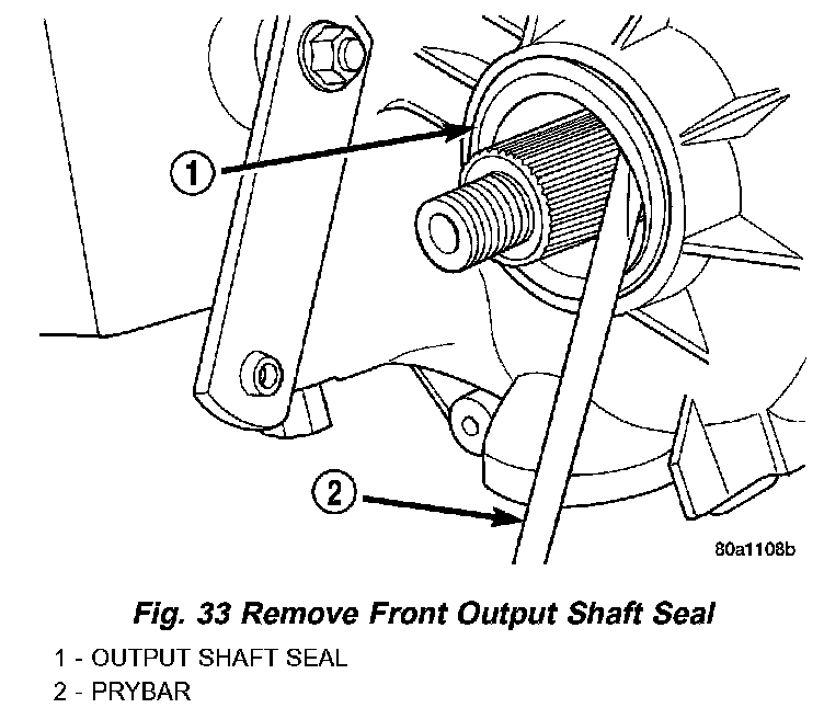
1. Remove front output shaft seal from front case with pry tool (Fig. 33).
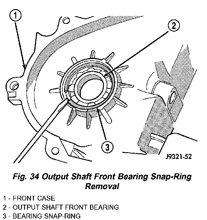
2. Remove snap-ring that retains front output shaft bearing in front case (Fig. 34).
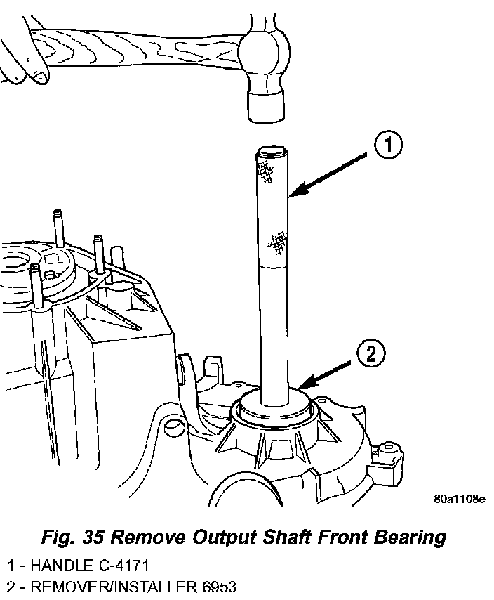
3. Using tool 6953, remove bearing from front case (Fig. 35).
4. Using tool 6953, install new bearing.
5. Install snap-ring to hold bearing into case.
6. Install new front output seal in front case with Installer Tool 6952-A as follows:
a. Place new seal on tool. Garter spring on seal goes toward interior of case.
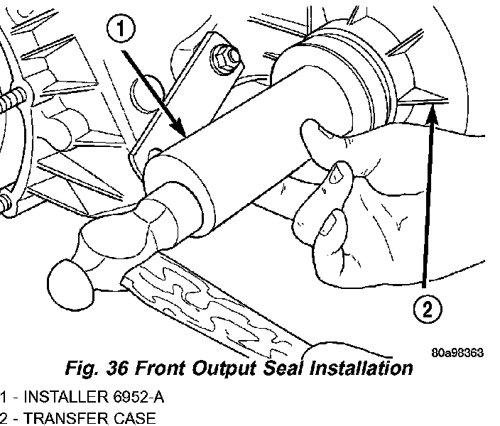
b. Start seal in bore with light taps from hammer (Fig. 36). Once seal is started, continue tapping seal into bore until installer tool bottoms against case.
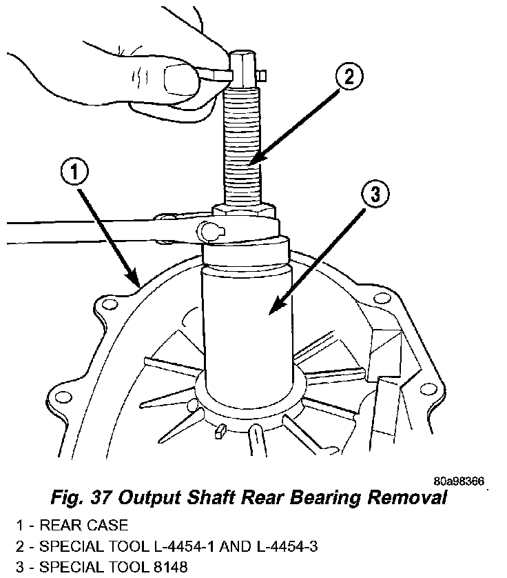
7. Remove the output shaft rear bearing with the screw and jaws from Remover L-4454 and Cup 8148 (Fig. 37).
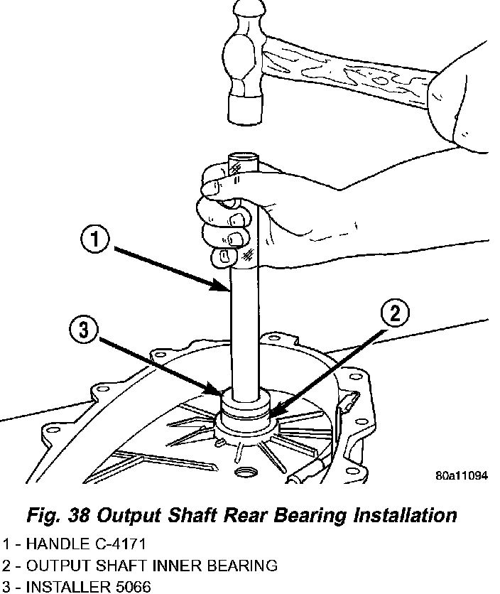
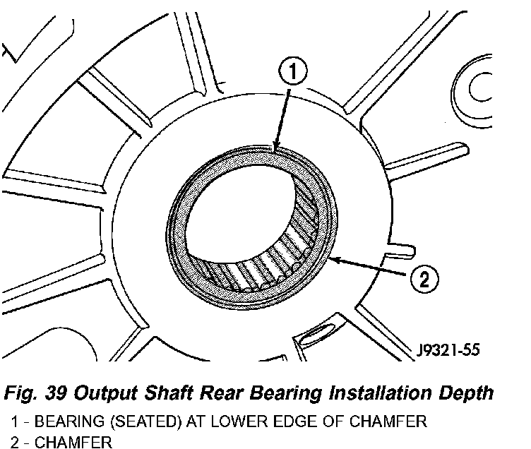
8. Install new bearing with Tool Handle C-4171 and Installer 5066 (Fig. 38). The bearing bore is chamfered at the top. Install the bearing so it is flush with the lower edge of this chamfer (Fig. 39).
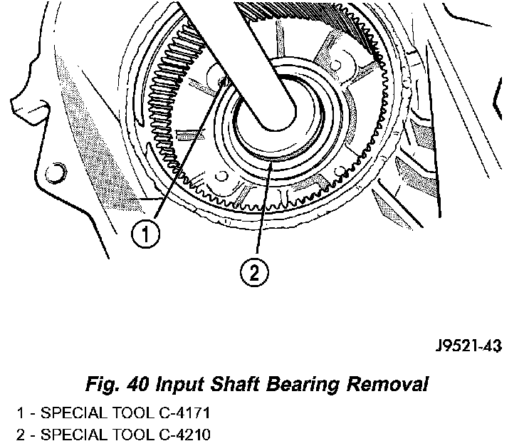
9. Using Remover C-4210 and Handle C-4171, drive input shaft bearing from inside the annulus gear opening in the case. (Fig. 40).
10. Install locating ring on new bearing.
11. Position case so forward end is facing upward.

12. Using Remover C-4210 and Handle C-4171, drive input shaft bearing into case. The bearing locating ring must be fully seated against case surface (Fig. 41).
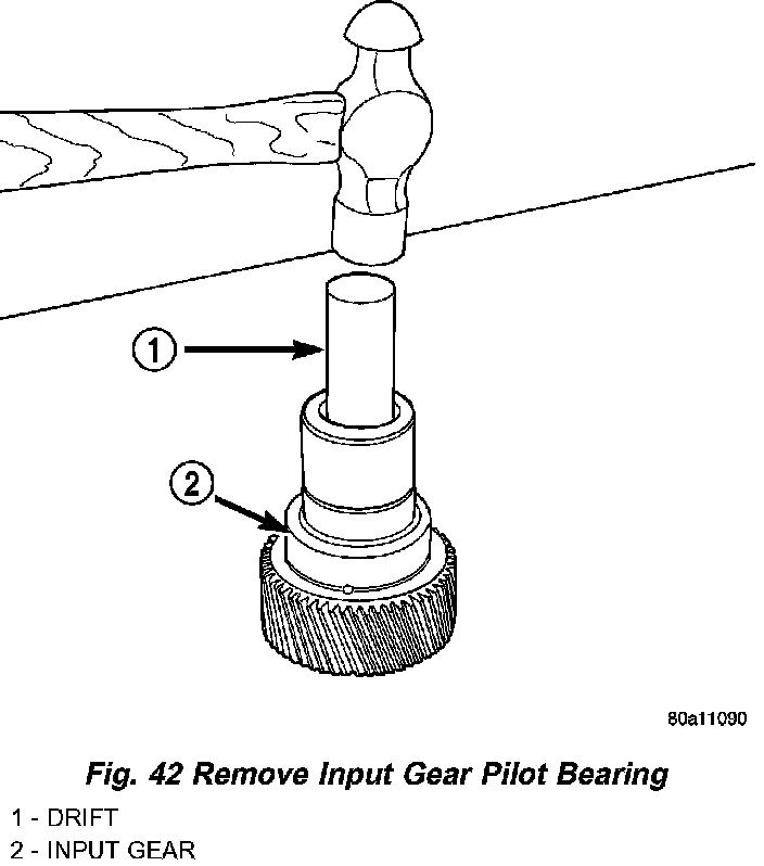
13. Remove input gear pilot bearing by inserting a suitably sized drift into the splined end of the input gear and driving the bearing out with the drift and a hammer (Fig. 42).
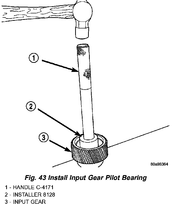
14. Install new pilot bearing with Installer 8128 and Handle C-4171 (Fig. 43).
15. Remove front bearing retainer seal with suitable pry tool.
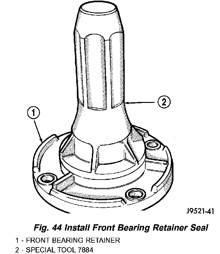
16. Install new front bearing retainer with Installer 7884 (Fig. 44).
INPUT AND LOW RANGE GEAR
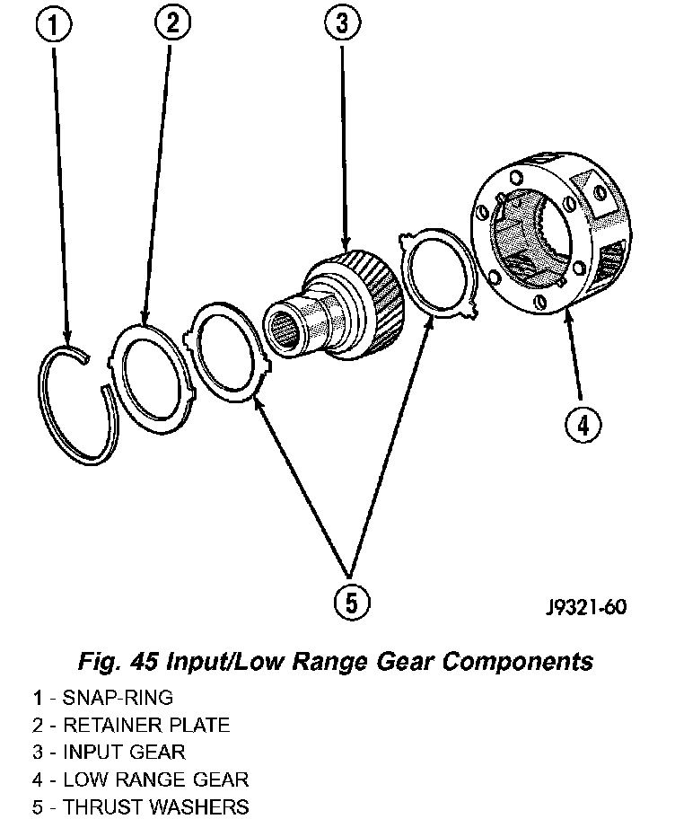
1. Lubricate gears and thrust washers (Fig. 45) with transfer case lubricant.
2. Install first thrust washer in low range gear (Fig. 45). Be sure washer tabs are properly aligned in gear notches.
3. Install input gear in low range gear. Be sure input gear is fully seated.
4. Install remaining thrust washer in low range gear and on top of input gear. Be sure washer tabs are properly aligned in gear notches.
5. Install retainer on input gear and install snap-ring.
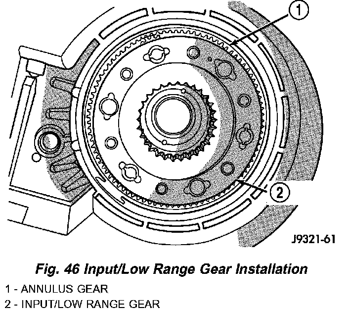
6. Align and install low range/input gear assembly in front case (Fig. 46). Be sure low range gear pinions are engaged in annulus gear and that input gear shaft is fully seated in front bearing.
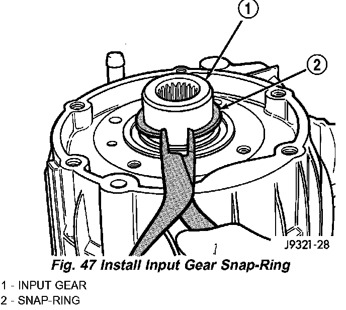
7. Install snap-ring to hold input/low range gear into front bearing (Fig. 47).
8. Clean gasket sealer residue from retainer and inspect retainer for cracks or other damage.
9. Apply a 3 mm (1/8 in.) bead of Mopar gasket maker or silicone adhesive to sealing surface of retainer.
10. Align cavity in seal retainer with fluid return hole in front of case.
CAUTION: Do not block fluid return cavity on sealing surface of retainer when applying Mopar gasket maker or silicone adhesive sealer. Seal failure and fluid leak can result.
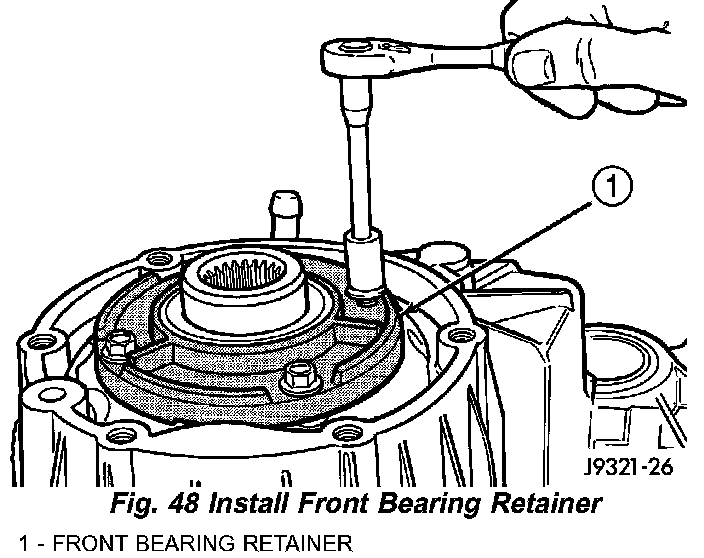
11. Install bolts to hold retainer to transfer case (Fig. 48). Tighten to 21 Nm (16 ft. lbs.) of torque.
SHIFT FORKS AND MAINSHAFT
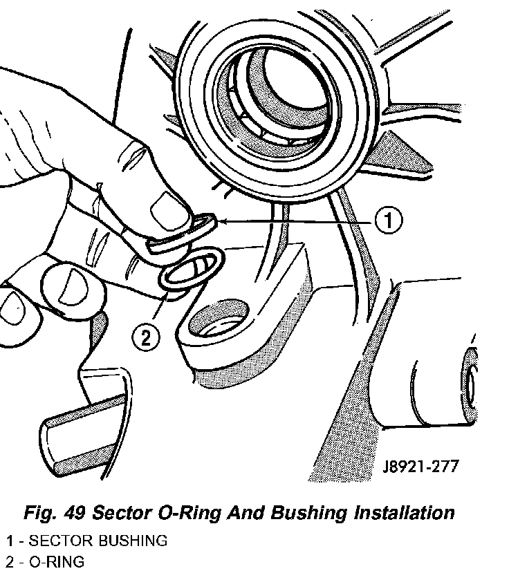
1. Install new sector shaft O-ring and bushing (Fig. 49).

2. Install shift sector (Fig. 50).
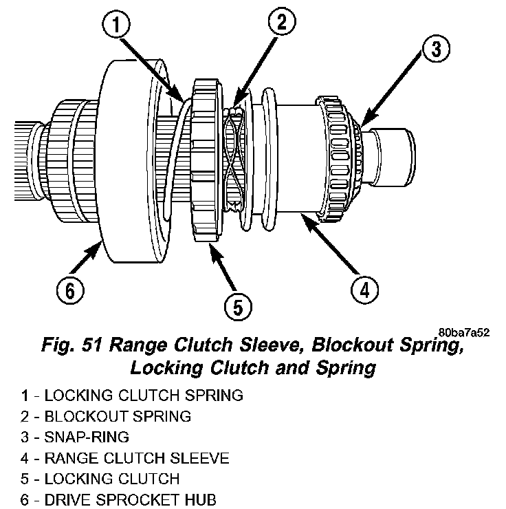
3. Install locking clutch spring, locking clutch, blackout spring, and range clutch sleeve, to mainshaft as shown in (Fig. 51). Install snap ring.
4. Install drive sprocket hub to mainshaft and manually load the needle bearings.
5. Install new pads on range fork, if necessary.
6. Install range shift fork to range clutch sleeve. Install mainshaft/range shift fork assembly into transfer case and input planetary assembly. Rotate fork until it engages with slot in shift sector.
7. Install shift rail to shift range fork and transfer case housing.
8. Rotate shift sector to NEUTRAL position.
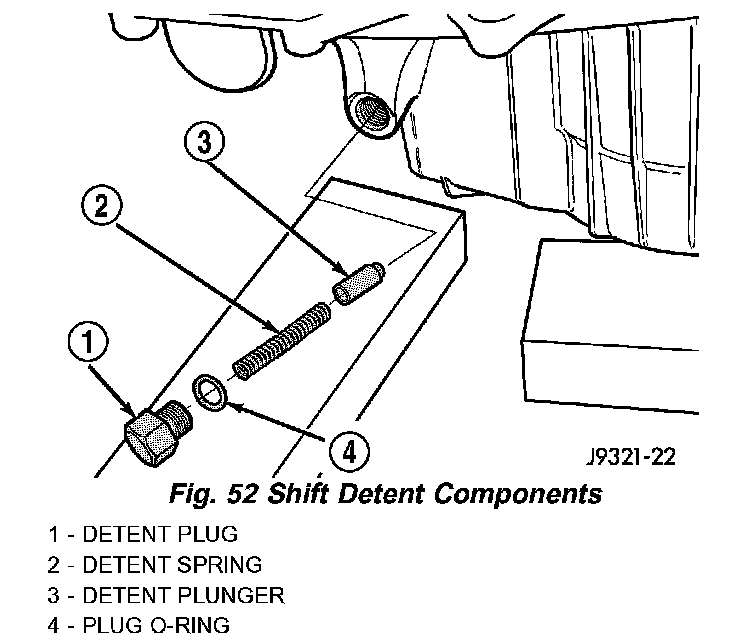
9. Install new O-ring on detent plug (Fig. 52).
10. Lubricate detent plunger with transfer case lubricant or light coat of petroleum jelly.
11. Install detent plunger, spring and plug (Fig. 52).
12. Verify that plunger is properly engaged in sector.
FRONT OUTPUT SHAFT AND DRIVE CHAIN
1. Lubricate front output shaft-sprocket assembly, drive chain and drive sprocket with transfer case lubricant.
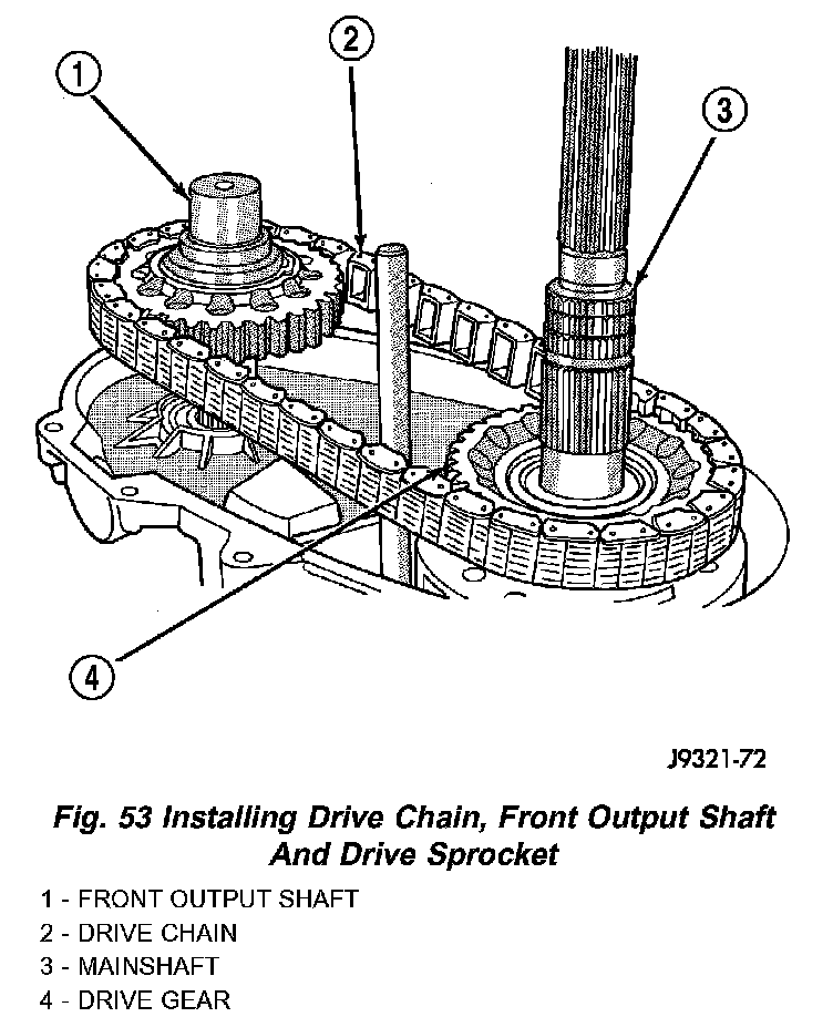
2. Assemble drive chain, drive sprocket and front output shaft (Fig. 53).
3. Start drive sprocket on mainshaft.
4. Guide front shaft into bearing and drive sprocket onto mainshaft drive gear (Fig. 53).
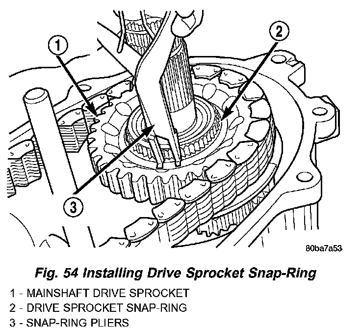
5. Install drive sprocket snap-ring (Fig. 54).
6. Install roller bearings if removed.
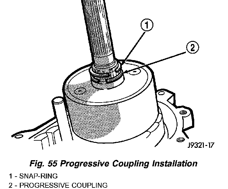
7. Install progressive coupling (Fig. 55).
8. Install the progressive coupling thrust washer over the output shaft and against the coupling.
9. Install the oil pump locating snap-ring onto the output shaft.

10. Install oil pickup tube in rear case. Be sure tube is seated in case notch as shown (Fig. 56).
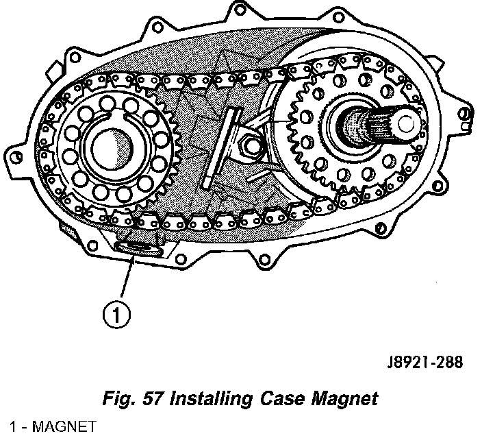
11. Install magnet in front case pocket (Fig. 57).
12. Clean sealing flanges of front case and rear case with a wax and grease remover.

13. Apply 3 mm (1/8 in.) wide bead of Mopar gasket maker or silicone adhesive sealer to mounting flange of front case. Work sealer bead around bolt holes as shown (Fig. 58).
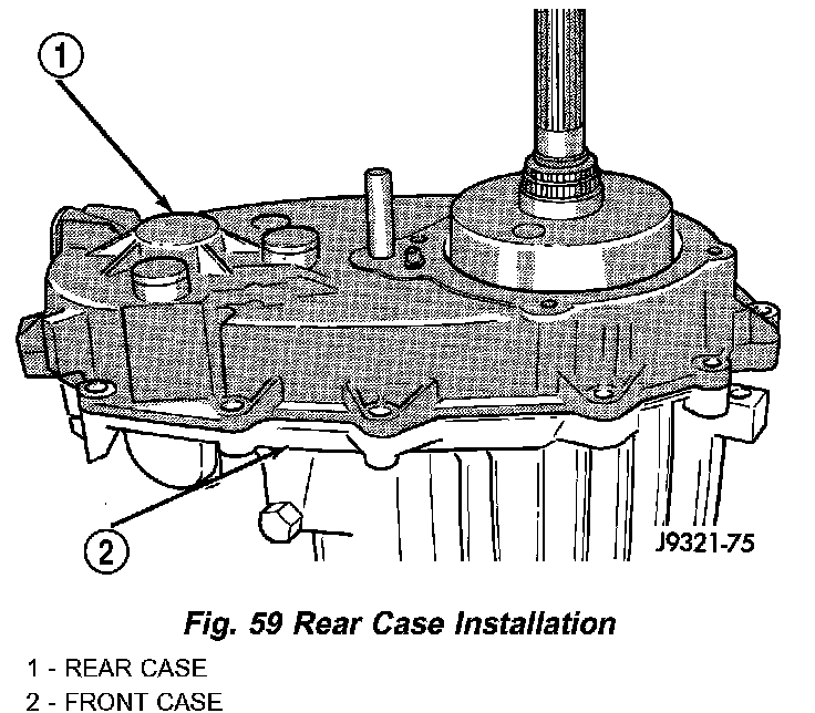
14. Align and install rear case on front case (Fig. 59).
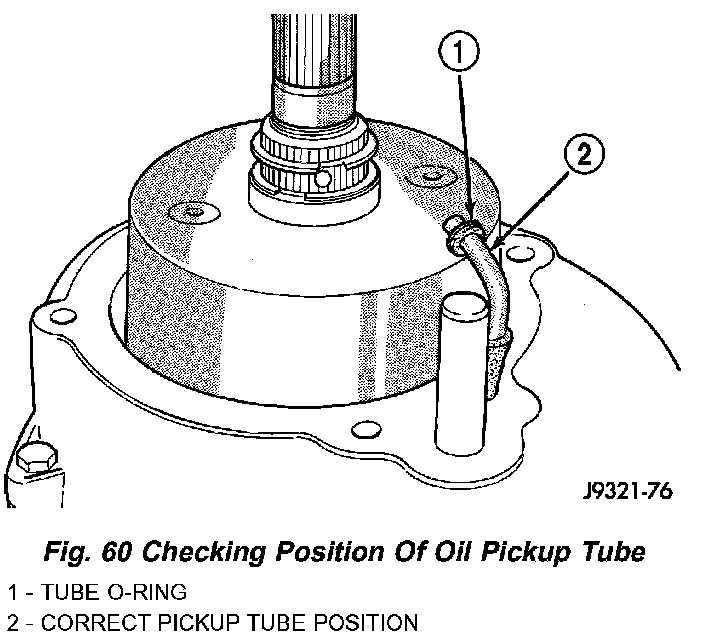
15. Verify that oil pickup tube is still seated in case notch and tube end is pointed toward mainshaft (Fig. 60).
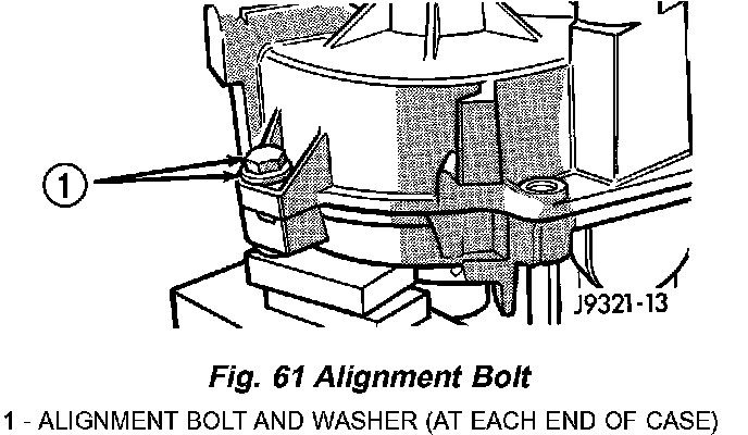
16. Install case attaching bolts. Alignment bolts at each end of case are only ones requiring washers (Fig. 61).
17. Tighten case bolts to 27 - 34 Nm (20 - 25 ft. lbs.) torque.
COMPANION FLANGE AND RANGE LEVER
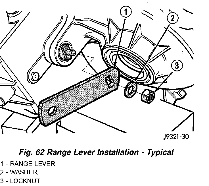
1. Install range lever, washer and locknut on sector shaft (Fig. 62). Tighten locknut to 27 - 34 Nm (20 - 25 ft. lbs.) torque.
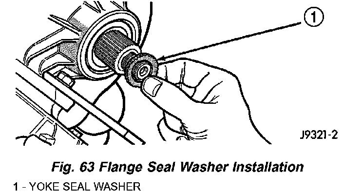
2. Install new seal washer on front output shaft (Fig. 63).
3. Lubricate flange hub with transfer case lubricant and install flange on front shaft.
4. Install new seal washer on front shaft.
5. Install companion flange and new nut on front output shaft.
6. Tighten flange nut to 122 - 176 Nm (90 - 130 ft. lbs.) torque. Use Tool C-3281, or similar tool to hold flange while tightening yoke nut.
REAR RETAINER AND OIL PUMP
1. Install new O-ring on flanged end of oil pickup tube.
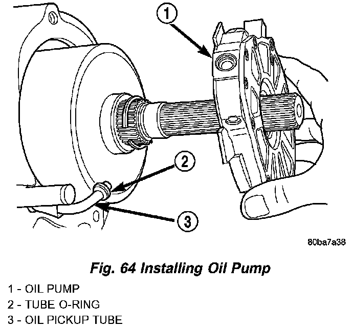
2. Install oil pump (Fig. 64).
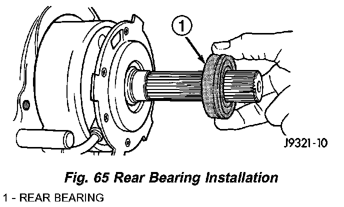
3. Insert oil pickup tube in pump (Fig. 65).
4. Install rear bearing on mainshaft (Fig. 65). Locating ring groove in bearing goes toward end of mainshaft.
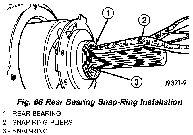
5. Install rear bearing retaining snap-ring (Fig. 66).
6. Install rear bearing locating ring in rear retainer, if ring was removed during overhaul.
7. Apply 3 mm (1/8 in.) wide bead of Mopar gasket maker or silicone adhesive sealer to mounting surface of rear retainer. Allow sealer to set-up slightly before proceeding.
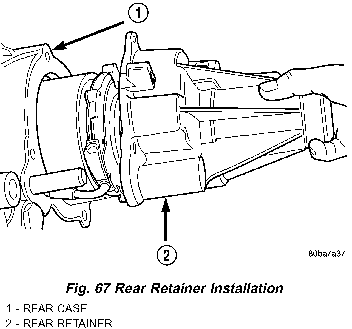
8. Slide rear retainer onto mainshaft (Fig. 67).
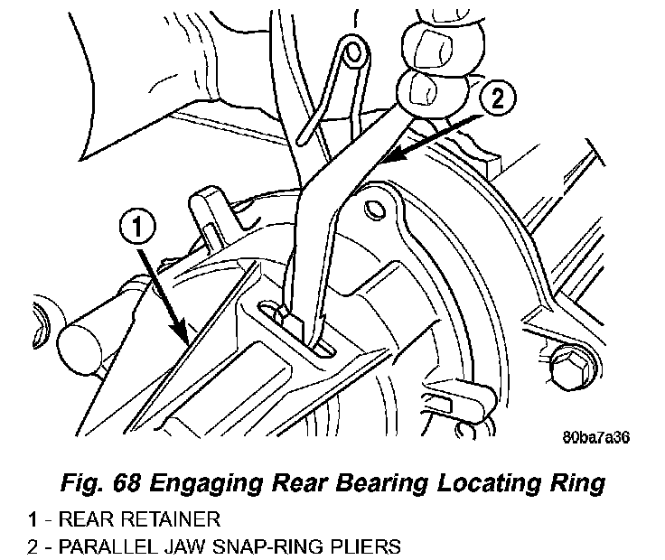
9. Spread rear bearing locating ring and slide rear retainer into place on rear case (Fig. 68).
10. Install and tighten rear retainer bolts to 27 - 34 Nm (20 - 25 ft. lbs.).
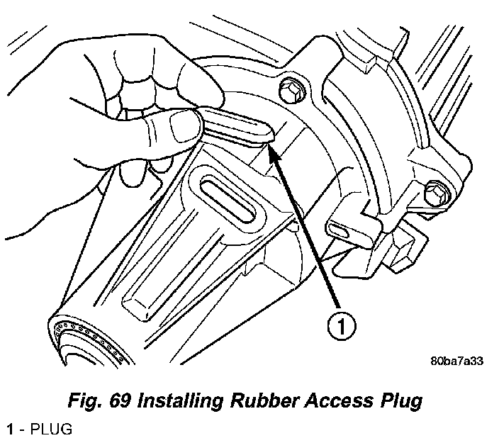
11. Install rubber access plug (Fig. 69).
FINAL ASSEMBLY
1. Install drain plug. Tighten plug to 41 - 54 Nm (30 - 40 ft. lbs.) torque.
2. Level transfer case and fill it with Mopar Transfer Case Lubricant. Correct fill level is to bottom edge of fill plug hole.
3. Install and tighten fill plug to 41 - 54 Nm (30 - 40 ft. lbs.) torque.
INSTALLATION
1. Mount transfer case on a transmission jack.
2. Secure transfer case to jack with chains.
3. Position transfer case under vehicle.
4. Align transfer case and transmission shafts and install transfer case on transmission.
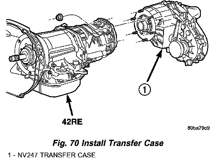
5. Install and tighten transfer case attaching nuts to 35 Nm (26 ft. lbs.) torque (Fig. 70).
6. Connect front propeller shaft and install rear propeller shaft.
7. Fill transfer case with correct fluid. Check transmission fluid level. Correct as necessary.
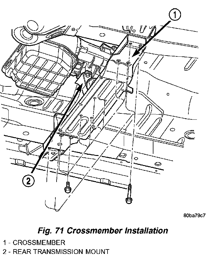
8. Install rear crossmember (Fig. 71) and skid plate, if equipped. Tighten crossmember bolts to 41 Nm (30 ft. lbs.) torque.
9. Remove transmission jack and support stand.
10. Verify transfer case is in NEUTRAL. Connect shift cable to transfer case range lever.
11. Lower vehicle and verify transfer case shift operation.
12. Adjust the transfer case shift cable, if necessary.