Fuel Tank: Service and Repair
REMOVALThis vehicle is equipped with an ORVR (On-Board Refueling Vapor Recovery) system. Because of this, the fuel tank may be drained the conventional way through the filler cap opening.
On this model, the fuel tank is mounted to the vehicle skid plate. The skid plate is mounted to vehicle body. The tank and skid plate are removed as 1 assembly.
1. Remove fuel filler cap.
2. Perform the Fuel System Pressure Release Procedure as described elsewhere in this group.
3. Disconnect negative battery cable.
4. Using an approved portable gasoline siphon/ storage tank, drain fuel from tank through filler cap opening.
Fig.16 Fuel Fill Hose At Body:
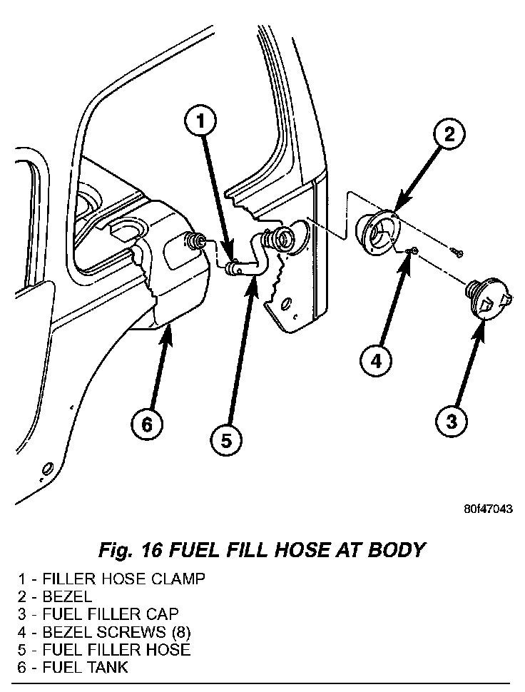
5. Remove 8 screws retaining plastic fuel filler bezel to body (Fig. 16). Remove plastic fuel filler bezel.
6. To prevent contaminants from entering tank, temporarily install fuel cap to fill hoses.
7. Remove right/rear tire/wheel.
8. Remove wheelhouse liner at right/rear wheel.
Fig.17 EVAP Canister/LDP Location:
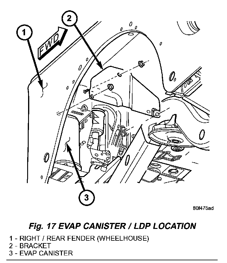
9. Remove vertical support bracket (Fig. 17) to gain access to 2 ORVR vapor lines.
Fig.18 Disconnecting ORVR Vapor Lines:
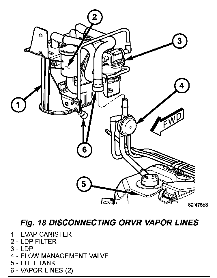
10. Two vapor lines connect the fuel tank to the EVAP canister and Leak Detection Pump (LDP). This connection is made near the right/rear corner of the fuel tank. Carefully disconnect these 2 vapor lines (Fig. 18) near top of flow management valve (Fig. 18). Be very careful not to bend or kink the vapor lines. If lines leak, a Diagnostic Trouble Code (DTC) will be set.
11. Cut plastic tie wrap securing rear axle vent hose to fuel fill hose.
Fig.19 Fuel Tank/Fuel Pump Module (Top View):

12. Disconnect fuel tank electrical connector at left/front of fuel tank (Fig. 19).
13. Disconnect 2 vapor lines (Fig. 19) at left/front of fuel tank.
14. Disconnect quick-connect fitting from fuel supply line at front of fuel tank (Fig. 19). Refer to Quick-Connect Fittings in this group for procedures.
15. The fuel tank and skid plate are removed as an assembly. Centrally position a transmission jack (or equivalent lifting device) under skid plate/fuel tank assembly. Secure tank assembly to jack.
Fig.21 Fuel Tank Mounting Nuts - Front:
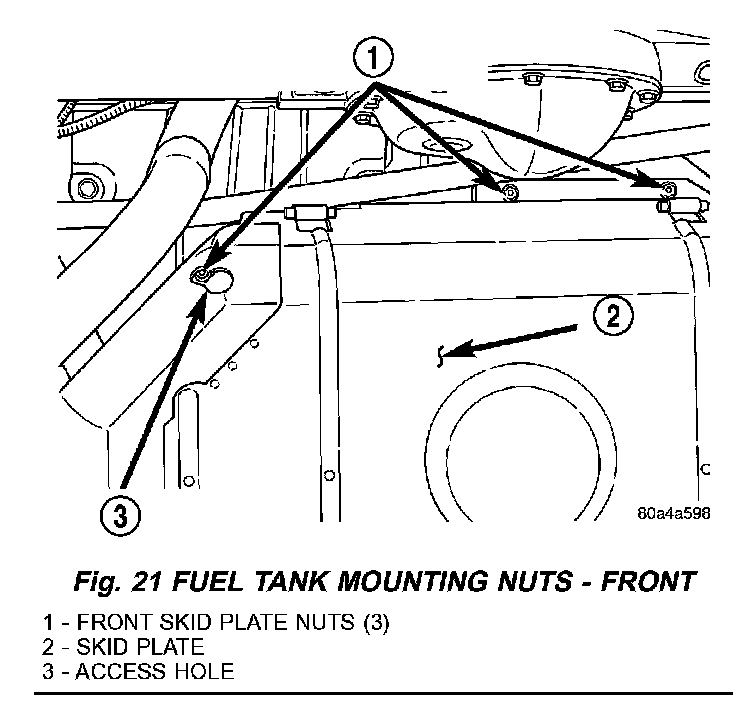
16. Remove three skid plate-to-body nuts at front of tank (Fig. 21). Remove one of the nuts through access hole on skid plate (Fig. 21).
Fig.20 Fuel Tank Mounting Nuts - Rear:
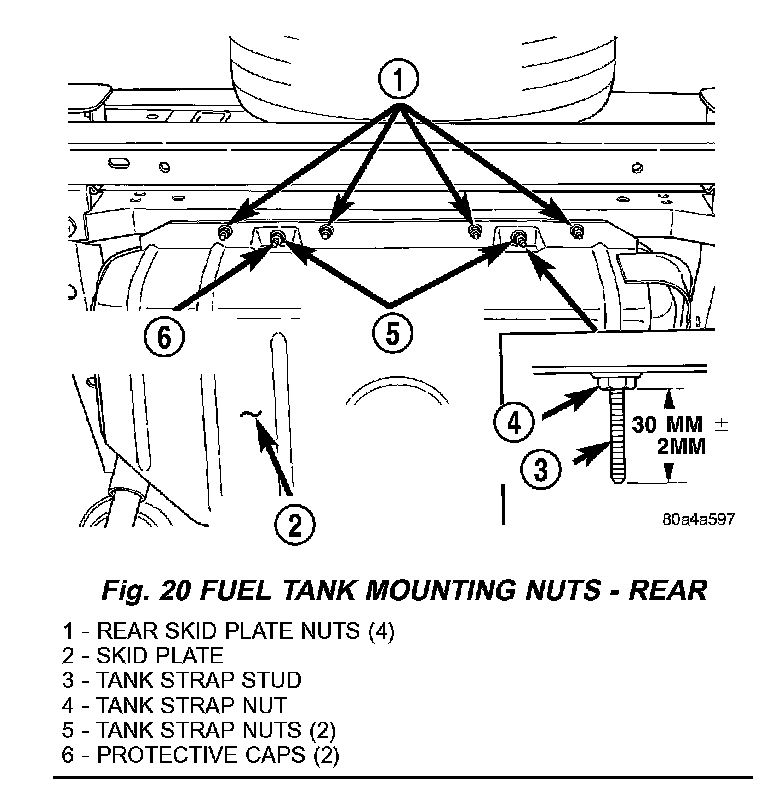
17. Remove four skid plate-to-body nuts at rear of tank (Fig. 20). Do not loosen tank strap nuts (Fig. 20).
18. Lower the tank assembly.
19. If fuel pump module is to be removed, refer to Fuel Pump Module Removal/Installation.
20. Disconnect fuel filler hose at tank. Before disconnecting, mark and note the hose rotational position in relation to tank fitting.
21. To separate tank from skid plate, remove two protective caps at tank strap studs (Fig. 20) and remove tank strap nuts.
22. Remove both straps and remove tank from skid plate.
INSTALLATION
1. If necessary, install fuel pump module to fuel tank. Refer to Fuel Pump Module Removal / Installation.
2. Place fuel tank into skid plate. Wrap straps around tank with strap studs inserted through holes in skid plate. Tighten strap nuts to attain 30 mm (± 2 mm) between bottom of nut to end of strap stud (Fig.20). Do not over tighten nuts.
3. Install two protective caps to tank strap studs.
4. Connect fuel fill hose at tank. Tighten hose clamp.
5. Raise skid plate/fuel tank assembly into position on body while carefully guiding plastic vapor lines and fill hose.
6. Install 7 skid plate mounting nuts. Tighten to 16 Nm (141 in. lbs.) torque.
7. Remove tank jacking device.
8. Carefully connect the 2 vapor lines (Fig. 18) near top of flow management valve (Fig. 18). Be very careful not to bend or kink the vapor lines. If lines leak, a Diagnostic Trouble Code (DTC) will be set.
9. Install EVAP canister bracket (Fig. 17).
10. Install wheelhouse liner at right/rear wheel.
11. Install right/rear tire/wheel.
12. Connect electrical connector at left/front of fuel tank.
13. Connect 2 vapor lines at left/front of fuel tank.
14. Connect quick-connect fitting to fuel supply line at left/front of fuel tank. Refer to Quick-Connect Fittings in this group for procedures.
15. Use a new plastic tie wrap to secure rear axle vent hose to fuel fill hose.
16. Position fuel fill bezel to body. Install 8 screws and tighten.
17. Fill fuel tank. Install filler cap.
18. Connect negative battery cable to battery
19. Start vehicle and inspect for leaks.