Part 2 of 2
Fig.1 Six-Way Power Seat Switches - Typical:

Fig.2 Ten-Way Power Seat Switches - Typical:

DRIVER SEAT SWITCH
Two different power seat switches are used on this vehicle, depending upon the optional power seat system installed in the vehicle. The six-way power seats are each equipped with a switch featuring three switch control knobs ganged together on the outboard seat cushion side shield. The ten-way power seats are each equipped with a switch featuring two knobs ganged together on the outboard seat cushion side shield.
The switch units for both power seat types are secured to the back of the seat cushion side shield with two screws. However, the control knobs for the six-way power seat switch unit remain installed during switch unit removal and installation, while both knobs for the ten-way power seat switch unit must be removed.
The individual switches in both power seat switch units cannot be repaired. If one switch is damaged or faulty, the entire power seat switch unit must be replaced.
The power seat tracks of both the six-way and the ten-way power seat systems can be adjusted in six different ways using the power seat switches. The ten-way system has the additional power seat recliner switch integral to the power seat switch and also has a separate, stand-alone switch to control the power lumbar adjuster. See the owner's manual in the vehicle glove box for more information on the power seat switch functions and the seat adjusting procedures.
When a power switch control knob or knobs are actuated, a battery feed and a ground path are applied through the switch contacts to the power seat track or recliner adjuster motor. The selected adjuster motor operates to move the seat track or recliner through its drive unit in the selected direction until the switch is released, or until the travel limit of the adjuster is reached. When the switch is moved in the opposite direction, the battery feed and ground path to the motor are reversed through the switch contacts. This causes the adjuster motor to run in the opposite direction.
No power seat switch should be held applied in any direction after the adjuster has reached its travel limit. The power seat adjuster motors each contain a self-resetting circuit breaker to protect them from overload. However, consecutive or frequent resetting of the circuit breaker must not be allowed to continue, or the motor may be damaged.
Ten-Way Power Seat Switches:

LUMBAR CONTROL SWITCH
The ten-way power seat option includes an electrically operated lumbar support mechanism. A single two-way momentary power lumbar switch is located on the outboard seat cushion side shield of each front seat, just forward of the other power seat switches. The power lumbar switch is secured to the back of the seat cushion side shield with two screws, and the switch paddle protrudes through a hole to the outside of the shield. The switch paddle is located in a shallow depression molded into the outer surface of the seat cushion side shield that helps to shroud it from unintentional actuation when entering or leaving the vehicle.
The power lumbar switches cannot be adjusted or repaired and, if faulty or damaged, they must be replaced.
When the power lumbar switch paddle is actuated, a battery feed and a ground path are applied through the switch contacts to the power lumbar adjuster motor. The motor operates to move the lumbar adjuster through its drive unit in the selected direction until the switch is released, or until the travel limit of the adjuster is reached. When the switch is moved in the opposite direction, the battery feed and ground path to the motor are reversed through the switch contacts. This causes the motor to run in the opposite direction.
The power lumbar switch should not be held applied in either direction after the adjuster has reached its travel limit. The power lumbar adjuster motor contains a self-resetting circuit breaker to protect it from overload. However, consecutive or frequent resetting of the circuit breaker must not be allowed to continue, or the motor may be damaged.
Fig.11 Power Lumbar Adjuster:

LUMBAR MOTOR
The ten-way power seat option includes an electrically operated lumbar support mechanism. The only visible evidence of this option is the separate power lumbar switch control paddle that is located on the outboard seat cushion side shield, just forward of the other power seat switch control knobs. The power lumbar adjuster and motor are concealed beneath the seat back trim cover and padding, where they are secured to a molded plastic back panel and to the seat back frame.
The power lumbar adjuster cannot be repaired, and is serviced only as a unit with the seat back frame. If the power lumbar adjuster or the seat back frame are damaged or faulty, the entire seat back frame unit must be replaced.
The power lumbar adjuster mechanism includes a reversible electric motor that is secured to the inboard side of the seat back panel and is connected to a worm-drive gearbox. The motor and gearbox operate the lumbar adjuster mechanism in the center of the seat back by extending and retracting a cable that actuates a lever. The action of this lever compresses or relaxes a grid of flexible slats. The more this grid is compressed, the more the slats bow outward against the center of the seat back padding, providing additional lumbar support.
Fig.12 WJ/WG Memory Select/Set Switch:
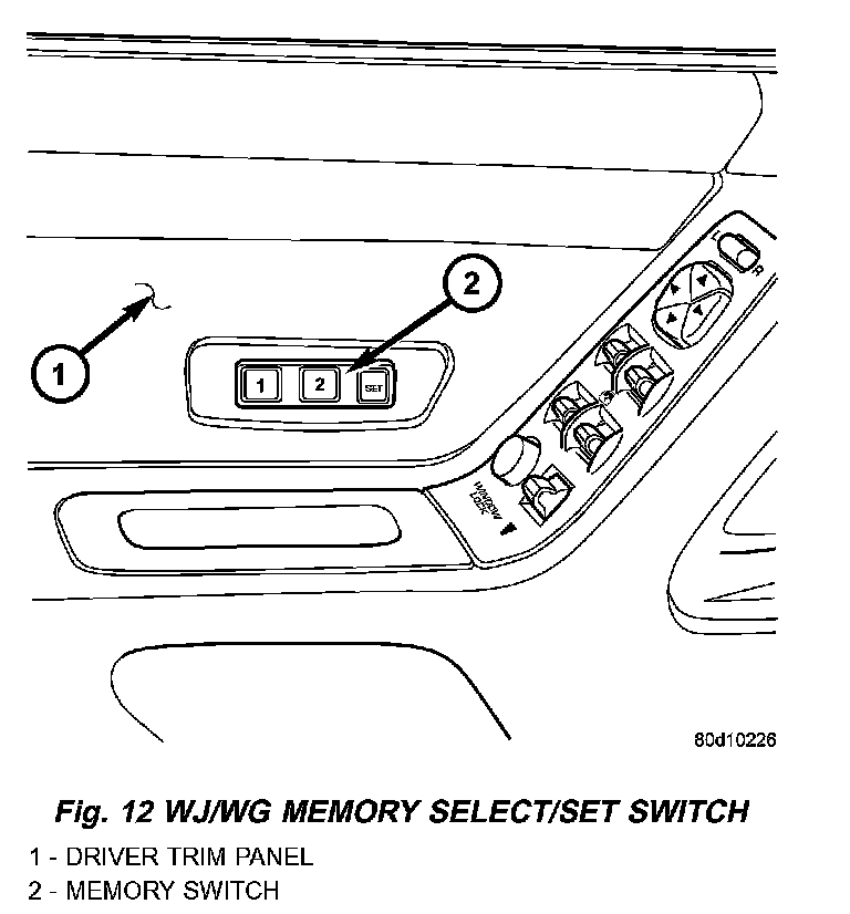
MEMORY SET SWITCH
Vehicles equipped with the memory system have a memory switch mounted to the driver side front door trim panel. This switch is used to set and recall all of the memory system settings for up to two drivers. The memory switch is a resistor multiplexed unit that is hard wired to the Driver Door Module (DDM), which is also located on the driver side front door trim panel. The DDM sends out the memory system set and recall requests to the other electronic modules over the Programmable Communications Interface (PCI) data bus.
The memory switch cannot be adjusted or repaired and, if faulty or damaged, it must be replaced. For complete circuit diagrams, refer to Wiring Diagrams.
The memory switch has three momentary switch buttons labeled Set, 1 and 2. The Driver 1 and Driver 2 buttons are back-lit with Light-Emitting Diodes (LED) for visibility, and are also color-coded to coincide with the color-coded Driver 1 and Driver 2 Remote Keyless Entry (RKE) transmitters. The Driver 1 memory switch button and RKE transmitter are black, and the Driver 2 memory switch button and RKE transmitter are gray. The memory switch Set button also has an LED that will illuminate and flash to indicate that the memory system is in the set mode. This LED will automatically be extinguished when a set request has been successfully completed.
See the owner's manual in the vehicle glove box for more information on the features, use and operation of the memory switch. For diagnosis of the memory switch, the DDM or the PCI data bus, the use of a DRB scan tool and the proper Diagnostic Procedures are recommended.
Six-Way Power Seat Switches:

Ten-Way Power Seat Switches:
PASSENGER SEAT SWITCH
Two different power seat switches are used on this vehicle, depending upon the optional power seat system installed in the vehicle. The six-way power seats are each equipped with a switch featuring three switch control knobs ganged together on the outboard seat cushion side shield. The ten-way power seats are each equipped with a switch featuring two knobs ganged together on the outboard seat cushion side shield.
The switch units for both power seat types are secured to the back of the seat cushion side shield with two screws. However, the control knobs for the six-way power seat switch unit remain installed during switch unit removal and installation, while both knobs for the ten-way power seat switch unit must be removed.
The individual switches in both power seat switch units cannot be repaired. If one switch is damaged or faulty, the entire power seat switch unit must be replaced.
The power seat tracks of both the six-way and the ten-way power seat systems can be adjusted in six different ways using the power seat switches. The ten-way system has the additional power seat recliner switch integral to the power seat switch and also has a separate, stand-alone switch to control the power lumbar adjuster. See the owner's manual in the vehicle glove box for more information on the power seat switch functions and the seat adjusting procedures.
When a power switch control knob or knobs are actuated, a battery feed and a ground path are applied through the switch contacts to the power seat track or recliner adjuster motor. The selected adjuster motor operates to move the seat track or recliner through its drive unit in the selected direction until the switch is released, or until the travel limit of the adjuster is reached. When the switch is moved in the opposite direction, the battery feed and ground path to the motor are reversed through the switch contacts. This causes the adjuster motor to run in the opposite direction.
No power seat switch should be held applied in any direction after the adjuster has reached its travel limit. The power seat adjuster motors each contain a self-resetting circuit breaker to protect them from overload. However, consecutive or frequent resetting of the circuit breaker must not be allowed to continue, or the motor may be damaged.
RECLINER MOTOR
The ten-way power seat option includes an electrically operated seat back recliner mechanism. The only visible evidence of this option is the separate power seat recliner switch control knob that is located on the outboard seat cushion side shield, just behind the other power seat switch control knob. The power seat recliner switch is integral to the ten-way power seat switch unit, but is actuated with a separate switch knob.
Power Seat Recliner And Track:

The power seat recliner unit is mounted in the place of a seat hinge on the outboard side of the seat. The upper hinge plate of the power seat recliner mechanism is secured with two screws to the seat back frame and is concealed beneath the seat back trim cover and padding. The lower hinge plate and the motor and drive unit of the power seat recliner mechanism is secured with two screws to the seat cushion frame, and is concealed by the outboard seat cushion side shield.
The power seat recliner cannot be repaired. If the unit is faulty or damaged, it must be replaced. Refer to Bucket Seat Recliner in Body for the service procedure.
The power seat recliner includes a reversible electric motor that is secured to the lower hinge plate of the recliner unit. The motor is connected to a gearbox that moves the upper hinge plate of the power seat recliner through a screw-type drive unit. The driver side power seat recliner motor used on models equipped with the optional memory system also has a position potentiometer integral to the motor assembly, which electronically monitors the motor position.
Power Seat Track - Typical:

POWER SEAT TRACK
Both the six-way and the ten-way power seat options include a single electrically operated power seat track unit located under each front bucket seat. The power seat track unit replaces the standard equipment manual seat tracks. The lower half of the power seat track is secured at the front with two screws to the floor panel seat cross member, and at the rear with two screws to the floor panel. Four nuts secure the bottom of the seat cushion frame to four studs on the upper half of the power seat track unit.
The power seat track unit cannot be repaired, and is serviced only as a complete unit. If any component in this unit is faulty or damaged, the entire power seat track unit must be replaced. Refer to Bucket Seat Track Adjuster in Body for the service procedure.
The power seat track unit includes three reversible electric motors that are secured to the upper half of the track unit. Each motor moves the seat adjuster through a combination of worm-drive gearboxes and screw-type drive units. Each of the three driver side power seat track motors used on models equipped with the optional memory system also has a position potentiometer integral to the motor assembly which electronically monitors the motor position.
The front and rear of the seat are operated by two separate vertical adjustment motors. These motors can be operated independently of each other, tilting the entire seat assembly forward or rearward; or, they can be operated in unison by selecting the proper power seat switch functions, which will raise or lower the entire seat assembly. The third motor is the horizontal adjustment motor, which moves the seat track in the forward and rearward directions.