Audio System - Poor Radio Reception
NUMBER: 08-021-05GROUP: Electrical
DATE: April 14, 2005
SUBJECT:
Poor Radio Reception - Signal May Ground At Antenna Base Due To Metal Debris
OVERVIEW:
This bulletin involves applying a specific size strip of electrical tape over top of the antenna base insulator. The tape will prevent the radio signal, from the insulated brass center conductor, from electrically grounding to the antenna base. The antenna base is already grounded to the vehicle body.
MODELS:
2005 (WK/WH) Grand Cherokee
NOTE:
This bulletin applies to vehicles built prior to March 20, 2005 (MDH 0320XX).
SYMPTOM/CONDITION:
The customer may notice that AM or FM radio station reception may be weaker than normal. This condition may include: static, reduced station range, or poor SEEK mode performance. This condition may be caused by a weak antenna signal. Part or all of the antenna signal may be grounding (lost) prior to receipt of the full signal at the radio.
The signal from the insulated antenna mast may be grounding to the already grounded antenna base.
The antenna mast connects to the threaded brass center conductor. The bright chrome antenna cap nut threads onto the brass center conductor. The act of threading the cap nut onto the brass center conduct may create and/or loosen metal filings. Each time the cap nut is threaded onto the center conductor additional metal filings may be produced.
A black insulator is molded into the antenna body. The insulator is used to isolate the brass center conductor (antenna mast signal) from the body grounded cast metal housing of the antenna base. Brass thread filings may fall from the center conductor and may create a ground path across the top surface of the antenna base insulator. The metal filings may be a "trail" of fine pieces of brass and/or thin strips of brass thread shavings. If present, the filings may move during vehicle use and cause intermittent signal reduction or loss.
DIAGNOSIS:
If the customer experiences one of the above conditions, perform the Repair Procedure.
NOTE:
This bulletin applies only to the AM and/or FM radio modes. Satellite radio is not addressed by this bulletin. This repair should be performed before further radio reception diagnosis is performed or radio replacement is considered.

PARTS REQUIRED

SPECIAL TOOLS/EQUIPMENT REQUIRED
REPAIR PROCEDURE:
1. Disconnect and isolate the negative battery cable from the battery.
2. Open the right front door.
3. Remove the antenna mast from the antenna base.
4. Remove the chrome antenna cap nut and black plastic trim ring.
5. Position the antenna base in the A-pillar opening created by the open door.
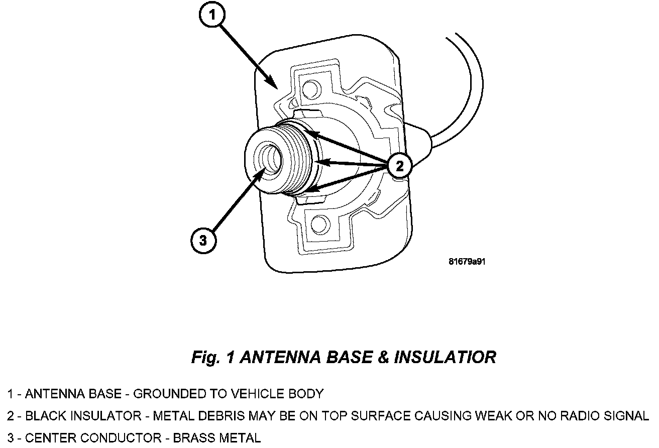
6. Thoroughly clean the antenna cap nut and the entire antenna base of any brass filings. Verify that no brass filings are present on the top surface of the molded-in black insulation in the antenna base (Fig. 1).
NOTE:
The cap nut, center conductor, and the antenna base insulator must be free of any metal filings.
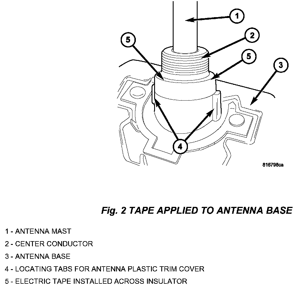
7. Locate the two locating tabs used to index the plastic trim ring to the antenna base (Fig. 2).
8. Install a 6.5 mm x 55 mm (1/4 in. X 2-1/4 in.) strip of electrical tape around the antenna base covering the molded-in insulator. Use the top of the two locating tabs as a guide for the lower side of the tape strip.
9. Once the tape is installed around the antenna base, carefully form the tape so that it takes the shape of the circular step around the antenna base.
10. Install the antenna base to the right fender.
11. Install the plastic trim ring to the antenna base.
12. Carefully hand thread the chrome cap nut as far as possible onto the antenna base. Tighten the cap nut to 4.5 Nm (40 in. lbs.). Verify that the cap nut is properly tightened.
13. Install the antenna mast to the antenna base.
14. From the A-pillar/right door opening, reposition the sound insulating foam panel between the inner and outer right fender (if equipped).
15. With a trim stick remove the right instrument panel side trim cover. Locate the antenna harness and connector. Disconnect the antenna side lead from the antenna harness connector. The conductors at the end of the antenna lead will be measured for resistance.
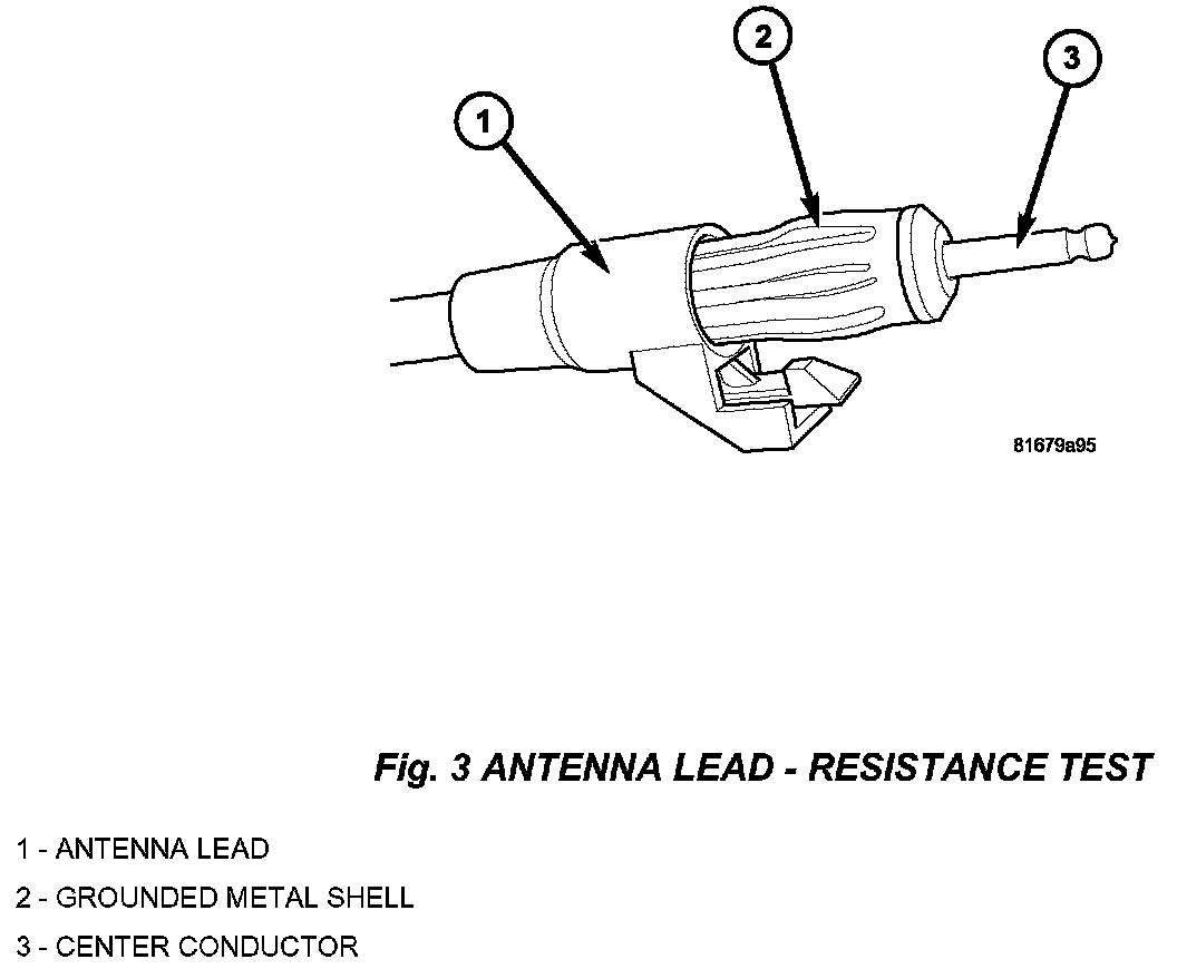
16. Using an ohmmeter, measure the resistance at the antenna lead connector between the center conductor and the grounded metal shell of the connector (Fig. 3).
17. Verify that there is NO continuity between the center conductor and the metal shell. The resistance should be greater than 1 Megaohms.
18. Connect the antenna lead to the antenna harness connector and install the right side instrument side panel trim cover.
19. Connect the negative battery cable to the battery and set the vehicle clock to the correct time.
POLICY:
Reimbursable within the provisions of the warranty.

TIME ALLOWANCE

FAILURE CODE
Disclaimer
This bulletin is supplied as technical information only and is not an authorization for repairs.