Connecting Rod: Service and Repair
PISTONREMOVAL
NOTE: Both the connecting rod and the connecting rod cap are paint marked to aid during assembly. Paint marks disappear after time. If the rod and the cap are not marked with paint, paint mark or scribe them before disassembly.
1. Disconnect negative battery cable.
2. Remove cylinder head.
3. Raise vehicle on hoist.
4. Remove oil pan.
5. Remove oil pump pickup tube.
6. Remove balance shaft assembly.
7. Remove top ridge of cylinder bores with a ridge reamer before removing pistons from cylinder block. Be sure to keep top of pistons covered during this operation.
8. Piston and connecting rods must be removed from top of cylinder block. Rotate crankshaft so that each connecting rod is centered in cylinder bore.
NOTE: Be careful not to nick or scratch crankshaft journals
9. After removal, install bearing cap on the mating rod and mark pistons with matching cylinder number when removed from engine block.
PISTON PIN - REMOVAL
1. Secure connecting rods in a soft jawed vice.
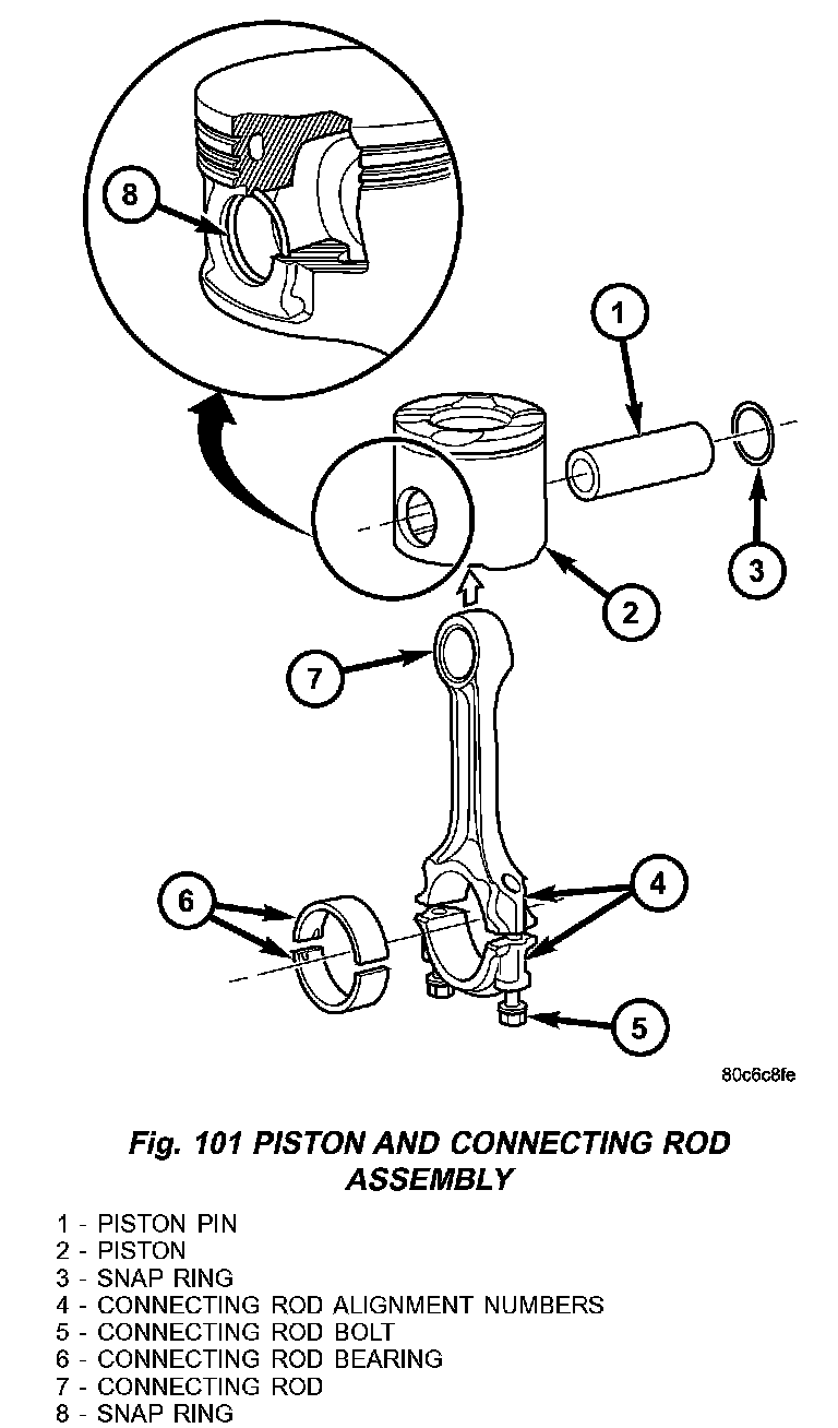
2. Remove 2 snap rings securing piston pin (Fig. 101).
3. Push piston pin out of piston and connecting rod (Fig. 101).
INSPECTION
PISTONS
1. Piston Diameter: Size: 91.912 - 91.928 mm (3.6185 - 3.6192 inch) Maximum wear limit 0.05mm (0.0019 inch).
2. Check piston pin bores in piston for roundness. Make 3 checks at 120° intervals. Maximum out of roundness 0.05 mm (0.0019 inch).
3. The piston diameter should be measured approximately 15 mm (0.590 inch) up from the base.
4. Skirt wear should not exceed 0.1 mm (0.00039 inch).
5. The clearance between the cylinder liner and piston should not exceed 0.065 - 0.083 mm (0.0025 - 0.0032 inch).
CONNECTING RODS
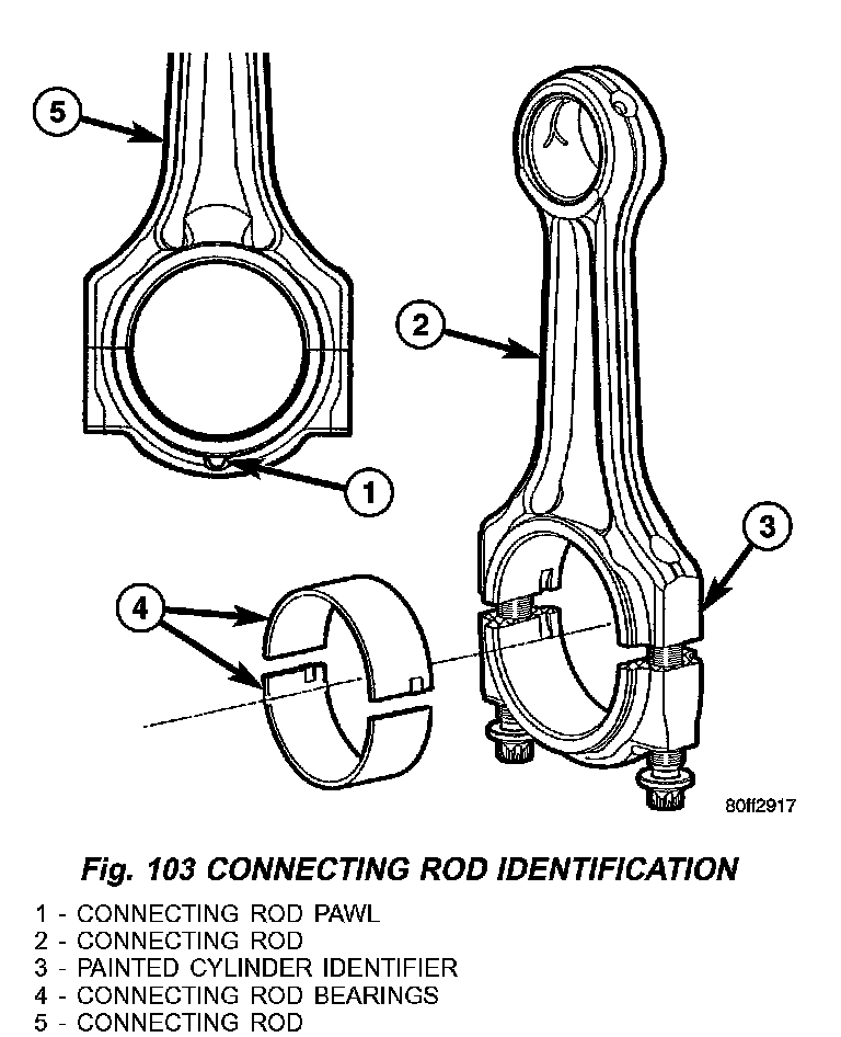
CAUTION: Connecting rod bolts must be replaced when disassembled. When assembling the connecting rod, be sure that the pawl on each of the connecting rod caps is facing the rear (fly wheel) side of the engine (Fig. 103).
NOTE: Do Not lubricate the new connecting rod bolts. They are already coated with a anti scuff treatment.
1. Assemble bearing shells and bearing caps to their respective connecting rods ensuring that the serrations on the cap and reference marks are aligned (Fig. 103).
2. Tighten connecting cap bolts to 10 Nm (88 inch lbs.).
3. Without loosening connecting rod bolts, tighten all bolts to 30 Nm (22 ft. lbs.).
4. Using a torque angle gauge, tighten each bolt an additional 40°.
5. Recheck all bolt tightening with a torque wrench set to 88 Nm (65 ft. lbs.).
6. Check and record internal diameter of crank end of connecting rod.
CAUTION: When changing connecting rods, DO NOT use a stamp to mark the cylinder location. Identify the connecting rods and caps location using a paint marker. All four must have the same weight and the same number. Replacement connecting rods will only be supplied in sets of four (Fig. 103).
Connecting rods are supplied in sets of four since they all must be of the same weight category. Max allowable weight difference is 5 gr.
PISTON PINS
1. Measure the diameter of piston pin in the center and both ends. Refer to Engine Specifications.
INSTALLATION
PISTON PIN INSTALLATION
1. Secure connecting rod in soft jawed vice.
2. Lubricate piston pin and piston with clean engine oil.
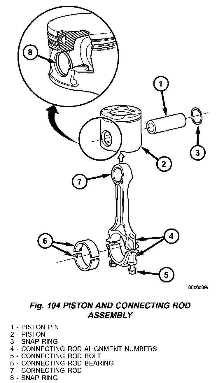
3. Position piston on connecting rod (Fig. 104).
CAUTION: Ensure arrow on piston crown and the bearing cap numbers on the connecting rod are on the opposite side.
4. Install piston pin (Fig. 104).
5. Install clips in piston to retain piston pin (Fig. 104).
6. Remove connecting rod from vice.
INSTALLATION
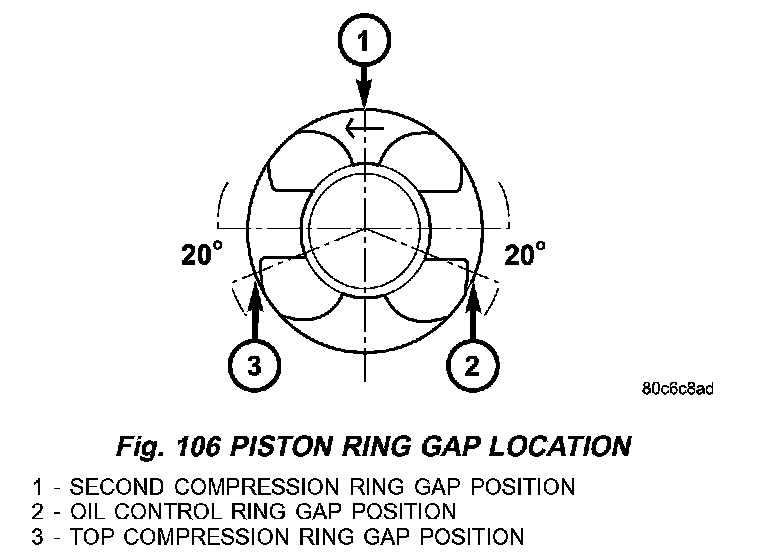
1. Before installing pistons, and connecting rod assemblies into the bore, be sure that compression ring gaps are staggered so that neither is in line with oil ring rail gap (Fig. 106).
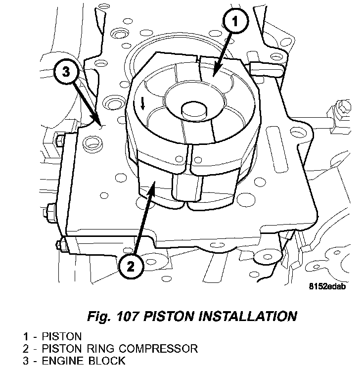
2. Before installing the ring compressor, make sure the oil ring expander ends are butted together (Fig. 107).
3. Immerse the piston head and rings in clean engine oil, slide the piston ring compressor, over the piston and tighten (Fig. 107). Ensure position of rings does not change during this operation.
4. Face arrow on piston towards front of engine.
CAUTION: Care must be taken not to nick crankshaft journal when installing pistons.
5. Rotate crankshaft so that the connecting rod journal is on the center of the cylinder bore. Insert rod and piston into cylinder bore and guide rod over the crankshaft journal (Fig. 107).
6. Guide the piston down in cylinder bore, using a hammer handle. At the same time, guide connecting rod into position on connecting rod journal.
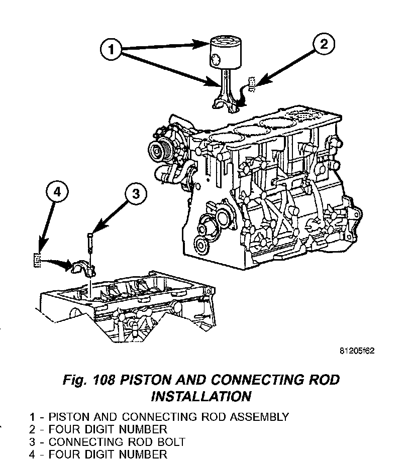
7. Install connecting rod caps (Fig. 108). Install rod bolts and torque to 10 Nm (88 inch lbs.). Torque bolts the next stage to 30 Nm (22 ft. lbs.) plus 60°. Then with a torque wrench set at torque to 88 Nm (65 ft. lbs.), make a tightening check.
8. Install cylinder head.
9. Install balance shaft assembly.
10. Install oil pump pickup tube.
11. Install oil pan.
12. Connect negative battery cable.