Engine Will Not Crank
ENGINE WILL NOT CRANKEngine Will Not Crank:
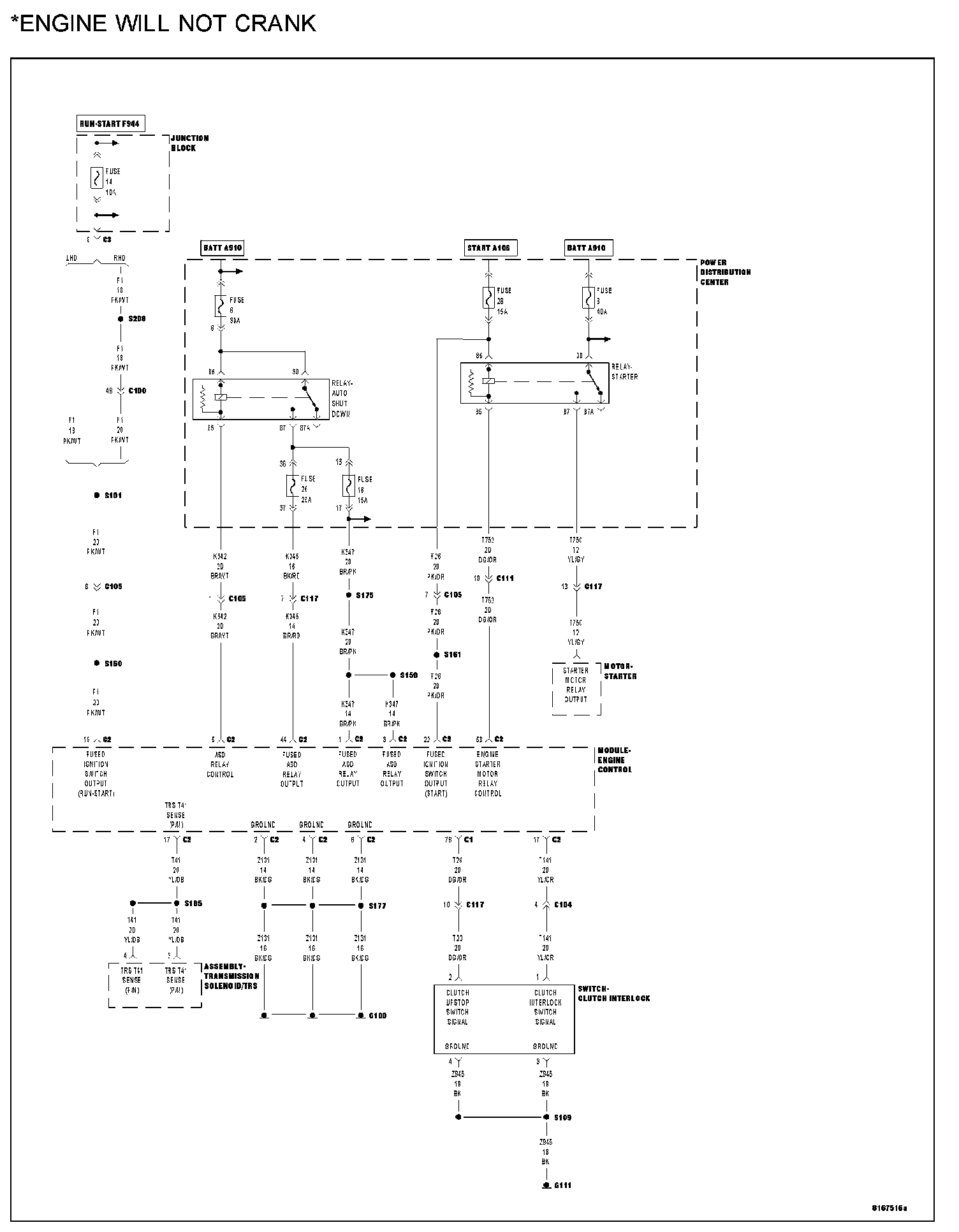
POSSIBLE CAUSES
- Battery cable high resistance
- Battery cables
- Clutch interlock switch
- Clutch interlock switch output circuit
- Ignition switch start output circuit open
- Mechanical problem
- Open fused battery (+) circuit
- Open ignition switch start output
- P/N switch
- P/N switch circuit open
- P/N switch ground circuit open
- SKIM codes present
- Starter motor
- Starter relay
- Starter relay
- Starter relay ground circuit open
- Starter relay output circuit open
DIAGNOSTIC TEST
1. BATTERY CABLES
Turn the ignition off.
NOTE: The battery must be fully charged before diagnosing a no crank condition.
Inspect the battery cables for corrosion, looseness or other problems.
Q: Is there evidence of problems?
YES: Repair as necessary.
Perform the ECM Verification Test Ver. 1. ECM Verification Test
NO: Go To 2
2. SKIM CODES PRESENT
Turn the ignition on.
With the scan tool, read the SKIM DTCs.
Q: Does the scan tool display any SKIM DTCs?
YES: Refer to symptom list for problems related to SKIM.
Perform the ECM Verification Test Ver. 1. ECM Verification Test
NO: Go To 3
3. AUTOMATIC OR MANUAL TRANSMISSION
Q: Is the vehicle equipped with an automatic transmission?
YES: Go To 4
NO: Go To 9
4. CHECKING STARTER OPERATION
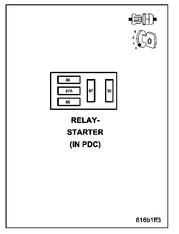
Turn the ignition off.
Remove the Starter Relay from the PDC.
WARNING:
- THE TRANSMISSION MUST BE IN PARK/NEUTRAL AND THE PARK BRAKE MUST BE SET FOR THIS TEST.
- THE ENGINE MAY CRANK IN THE NEXT STEP. WHEN THE ENGINE IS CRANKING, DO NOT STAND IN A DIRECT LINE WITH THE FAN. DO NOT PUT YOUR HANDS NEAR THE PULLEYS, BELTS OR FAN. DO NOT WEAR LOOSE CLOTHING.
Momentarily jumper Starter Relay connector cavities 30 and 87 in the PDC connector.
Q: Did the engine crank?
YES: Go To 5
NO: Go To 14
5. OPEN IGNITION SW START CIRCUIT
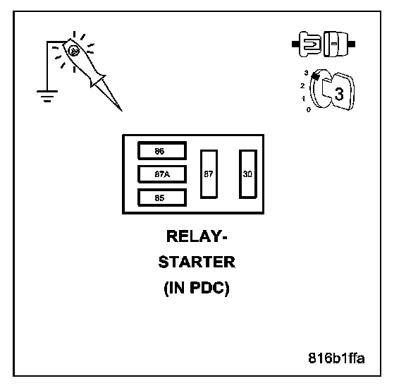
Place the transmission in Park or Neutral.
Remove the Starter Relay from the PDC.
Using a 12-volt test light connected to ground, check the Ignition Switch Start Output circuit while turning the ignition switch to the START position.
Q: Does the test light illuminate with the ignition switch in the START position?
YES: Go To 6
NO: Repair the Ignition Switch Start Output circuit between the Starter Relay and the ECM for an open.
Perform the ECM Verification Test Ver. 1. ECM Verification Test
6. STARTER RELAY
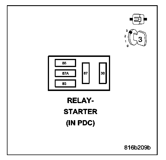
Turn the ignition off.
Remove the Starter Relay from the PDC.
Install a substitute relay in place of the Starter Relay.
Attempt to start the engine.
Q: Does the engine crank?
YES: Replace the Starter Relay.
Perform the ECM Verification Test Ver. 1. ECM Verification Test
NO: Go To 7
7. TRS SWITCH
Use the scan tool to monitor the status of the Transmission Range Switch (TRS).
Shift the vehicle from park to neutral.
Q: Does the TRS status change?
YES: Go To 8
NO: Replace the TRS.
Perform the ECM Verification Test Ver. 1. ECM Verification Test
8. TRS CIRCUIT OPEN/SHORT
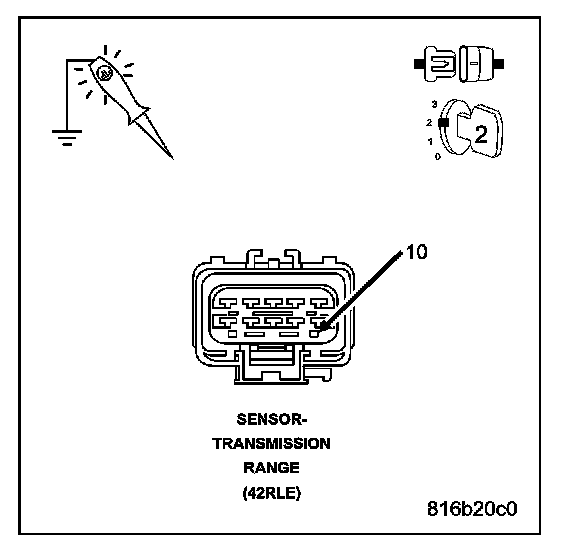
Turn the ignition off.
Disconnect the TRS harness connector.
Turn the ignition on.
Using a 12-volt test light connected to ground, check the (T41) TRS sense circuit.
Q: Does the test light illuminate brightly?
YES: Repair the (T41) Switch Sense circuit between the (T41) TRS Switch and the (cavity B17) ECM.
Perform the ECM Verification Test Ver. 1. ECM Verification Test
NO: Repair the P/N Switch Ground circuit for an open.
Perform the ECM Verification Test Ver. 1. ECM Verification Test
9. CHECKING STARTER OPERATION
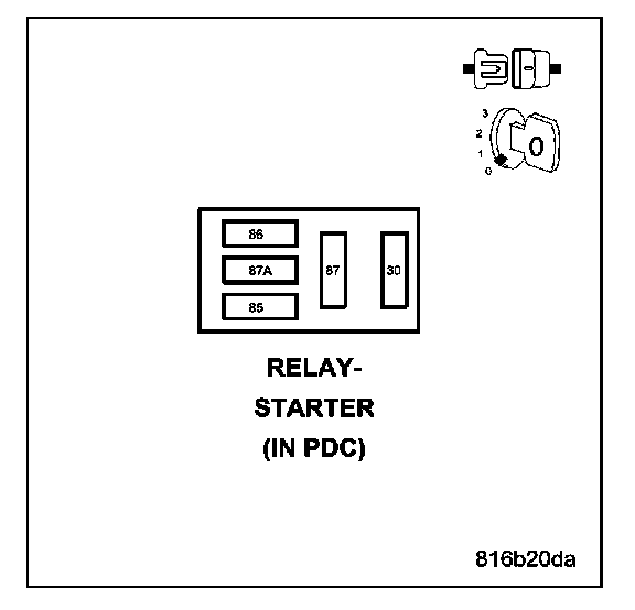
Turn the ignition off.
Remove the Starter Relay from the PDC.
WARNING:
- THE TRANSMISSION MUST BE IN NEUTRAL AND THE PARK BRAKE MUST BE SET FOR THIS TEST.
- THE ENGINE MAY CRANK IN THE NEXT STEP. WHEN THE ENGINE IS CRANKING, DO NOT STAND IN A DIRECT LINE WITH THE FAN. DO NOT PUT YOUR HANDS NEAR THE PULLEYS, BELTS OR FAN. DO NOT WEAR LOOSE CLOTHING.
Momentarily jumper Starter Relay connector cavities 30 and 87 in the PDC connector.
Q: Did the engine crank?
YES: Go To 10
NO: Go To 14
10. OPEN IGNITION SW START CIRCUIT
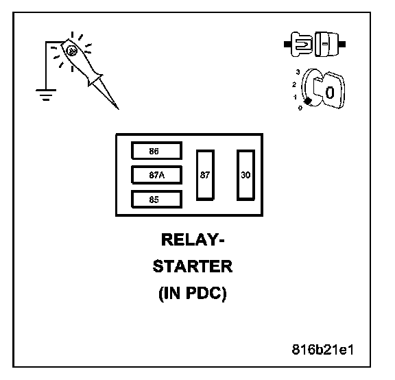
Remove the Starter Relay from the PDC.
Using a 12-volt test light connected to ground, check the (Cavity 86) Ignition Switch Start Output circuit while fully depressing the clutch pedal and turning the ignition switch to the START position.
Q: Does the test light illuminate with the ignition switch in the START position?
YES: Go To 11
NO: Go To 12
11. STARTER RELAY
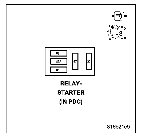
Turn the ignition off.
Remove the Starter Relay from the PDC.
Install a substitute relay in place of the Starter Relay.
Attempt to start the engine.
Q: Does the engine crank?
YES: Replace the Starter Relay.
Perform the ECM Verification Test Ver. 1. ECM Verification Test
NO: Repair the Starter Relay Ground Circuit for an open.
Perform the ECM Verification Test Ver. 1. ECM Verification Test
12. CLUTCH INTERLOCK SWITCH
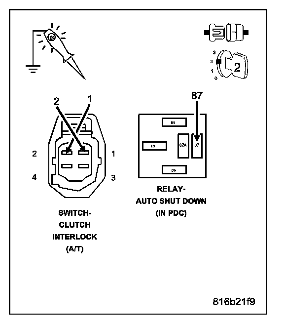
Turn the ignition off.
Remove the Starter Relay from the PDC.
Disconnect the Clutch Interlock Switch harness connector.
Connect a jumper wire across the Clutch Interlock Switch harness connector.
Using a 12-volt test light connected to ground, check the Ignition Switch Start Output circuit at the Starter Relay connector in the PDC and turning the ignition switch to the Start position.
Q: Does the test light illuminate with the ignition switch in the Start position?
YES: Replace the Clutch Interlock Switch.
Perform the ECM Verification Test Ver. 1. ECM Verification Test
NO: Go To 13
13. CLUTCH INTERLOCK SWITCH OUTPUT CIRCUIT OPEN
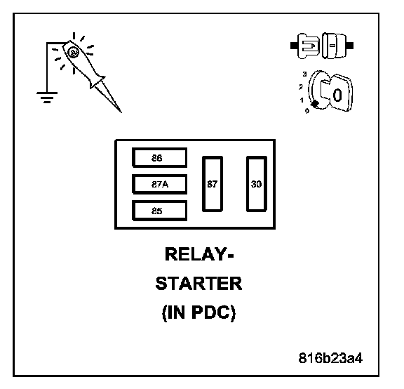
Turn the ignition off.
Disconnect the Clutch Interlock Switch harness connector.
Remove the Starter Relay from the PDC.
Measure the resistance of the Clutch Interlock Switch Output circuit between the PDC and the Clutch Interlock Switch harness connector.
Q: Is the resistance below 10.0 ohms?
YES: Repair the Ignition Switch Start Output circuit to the Clutch Interlock Switch.
Perform the ECM Verification Test Ver. 1. ECM Verification Test
NO: Repair the Clutch Interlock Switch Output circuit for an open.
Perform the ECM Verification Test Ver. 1. ECM Verification Test
14. OPEN FUSED BATTERY (+) CIRCUIT
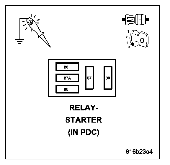
Remove the Starter Relay from the PDC.
Using a 12-volt test light connected to ground, check the (cavity 30) Fused B+ circuit in the Starter Relay connector in the PDC.
Q: Is the test light on?
YES: Go To 15
NO: Repair the Fused B(+) circuit for an open.
Perform the ECM Verification Test Ver. 1. ECM Verification Test
15. STARTER RELAY OUTPUT CIRCUIT OPEN
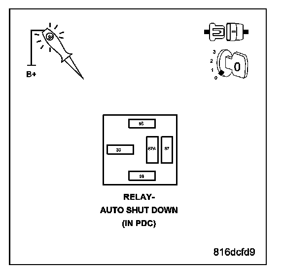
Turn the ignition off.
Remove the Starter Relay from the PDC.
Disconnect the Starter Relay Output wire from the Starter Solenoid.
Connect the Starter Relay Output wire (at the Starter) to ground.
Using a 12-volt test light connected to 12-volts, check the Starter Relay Output circuit at the Starter Relay connector in the PDC.
Q: Does the test light illuminate brightly?
YES: Go To 16
NO: Repair the Starter Relay Output circuit for an open.
Perform the ECM Verification Test Ver. 1. ECM Verification Test
16. BATTERY CABLE HIGH RESISTANCE
Check the battery cables for high resistance.
Q: Did either battery cable have a voltage drop greater than 0.2 volts?
YES: Replace the battery cable(s).
Perform the ECM Verification Test Ver. 1. ECM Verification Test
NO: Go To 17
17. MECHANICAL PROBLEM
Turn the ignition off.
Attempt to manually rotate the crankshaft 360 degree.
Q: Is the crankshaft able to rotate 360 degree?
YES: Replace the Starter Motor.
Perform the ECM Verification Test Ver. 1. ECM Verification Test
NO: Repair the engine mechanical problem.
Perform the ECM Verification Test Ver. 1. ECM Verification Test