Assembly
AUTOMATIC TRANSMISSION - 42RLEASSEMBLY
NOTE: If the transmission assembly is being reconditioned (clutch/seal replacement) or replaced, it is necessary to perform the Quick Learn Procedure using the DRBIII Scan Tool.
Fig. 79 Bearing Cup Installation Special Tool - 5050A:
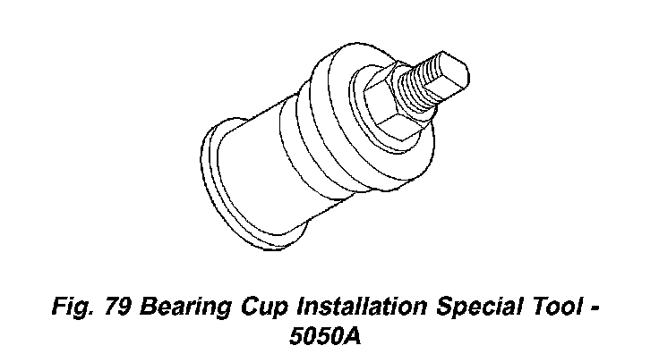
1. Install the output bearing cups using Special Tool - 5050A (Fig. 79).
Fig. 80 Install Piston Retainer Gasket:
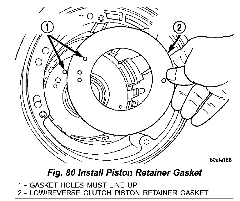
2. Install low/reverse piston retainer gasket (Fig. 80).
Fig. 81 Install Piston Retainer:
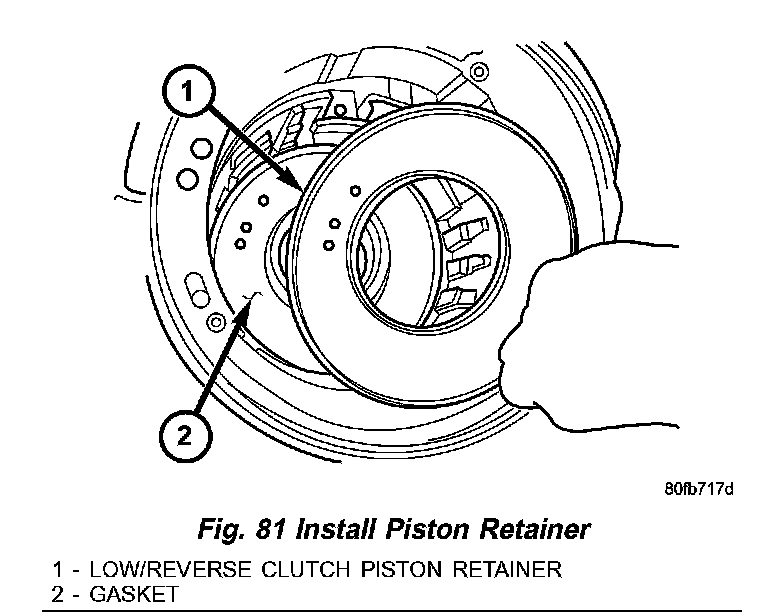
3. Install low/reverse piston retainer (Fig. 81).
Fig. 82 Install Retainer Attaching Screws:
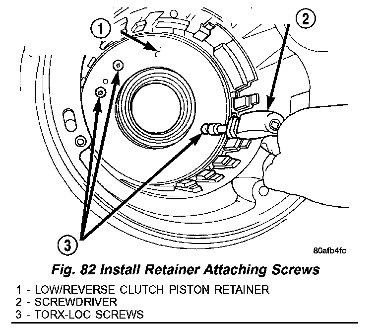
4. Install low/reverse piston retainer-to-case screws (Fig. 82) and torque to 5 Nm (45 inch lbs.).
NOTE: The Low/Reverse Clutch Piston has bonded seals which are not individually serviceable. Seal replacement requires replacement of the piston assembly.
Fig. 83 Install Low/Reverse Clutch Piston:
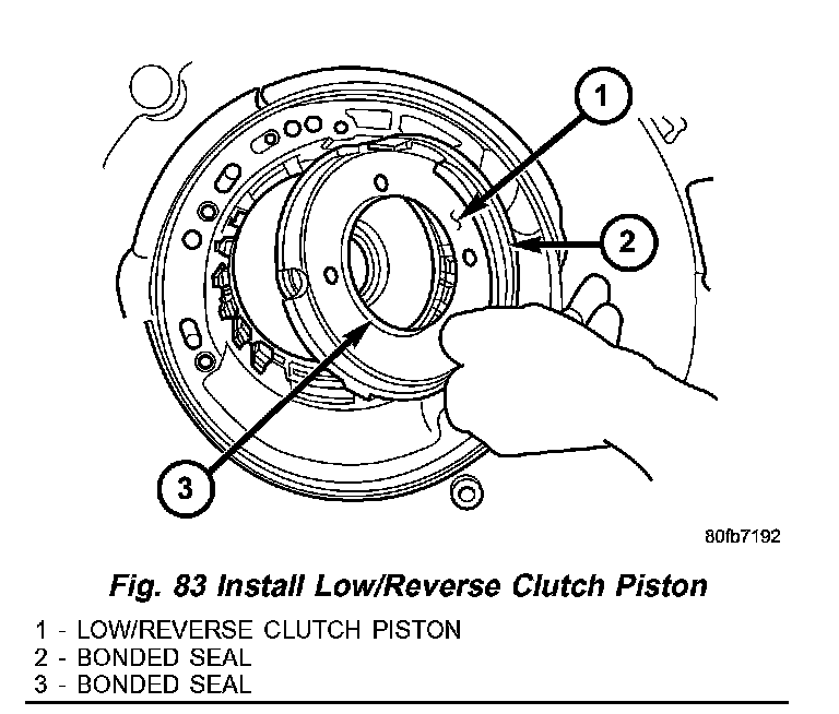
5. Install low/reverse clutch piston (Fig. 83).
Fig. 84 Guide Bracket Assembly:
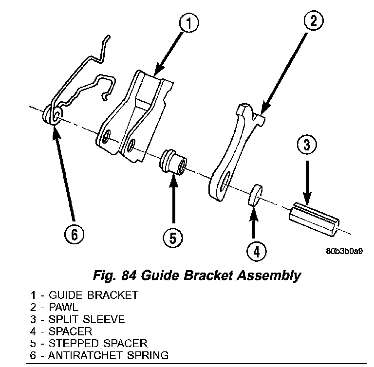
Fig. 85 Guide Bracket:
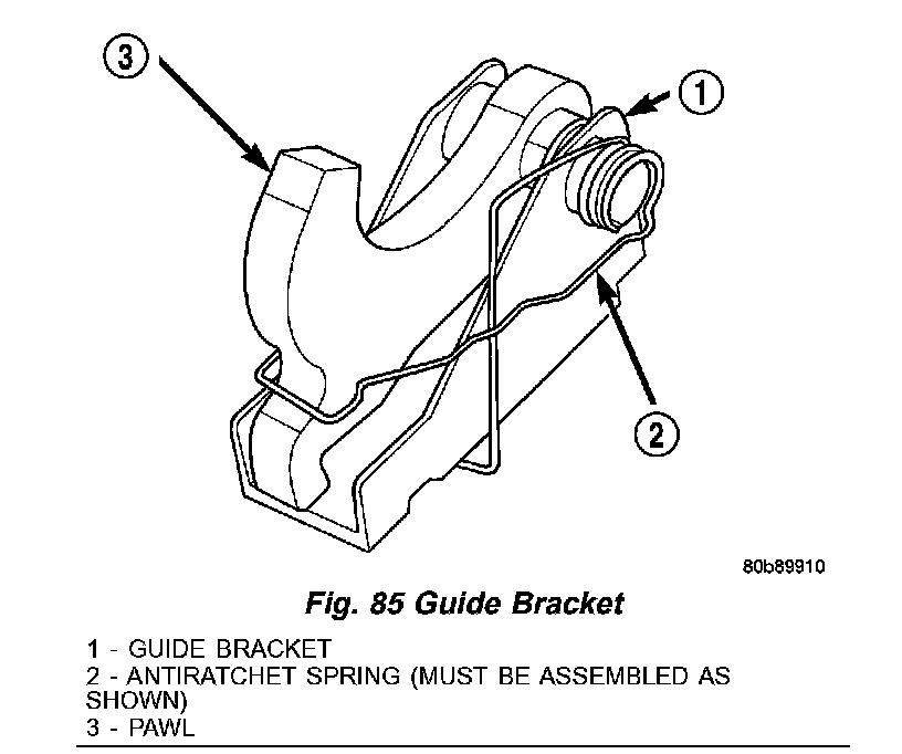
6. Assemble guide bracket assembly as shown in (Fig. 84) (Fig. 85).
Fig. 86 Install Guide Bracket Pivot Pin:
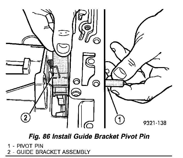
7. Install guide bracket pivot shaft (Fig. 86).
CAUTION: When installing, be sure guide bracket and split sleeve touch the rear of the transmission case.
8. Install park sprag pivot retaining screw and torque to 4.5 Nm (40 inch lbs.).
Fig. 87 Install Low/Reverse Piston Return Spring:
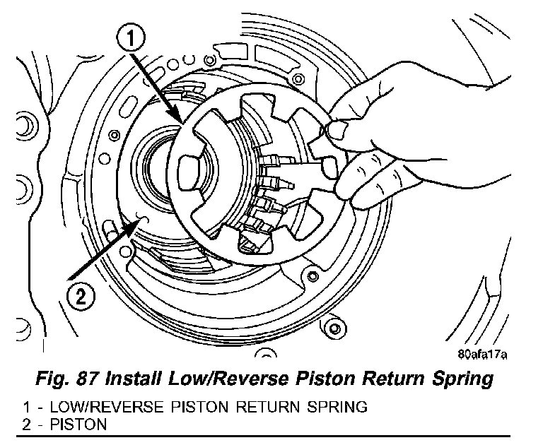
9. Install low/reverse piston Belleville spring into position (Fig. 87).
Fig. 88 Low/Reverse Spring Compressor Tool:
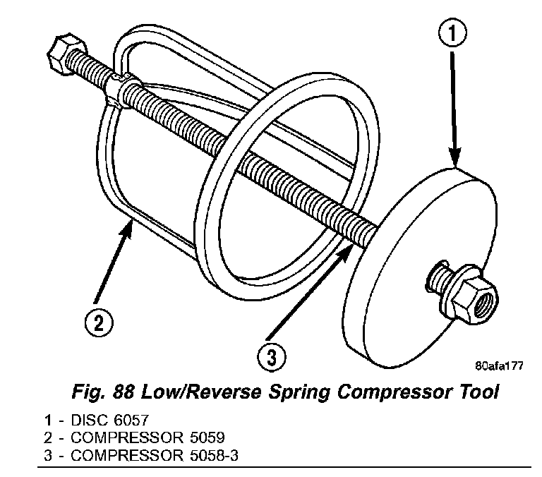
Fig. 89 Compressor Tool in Use:
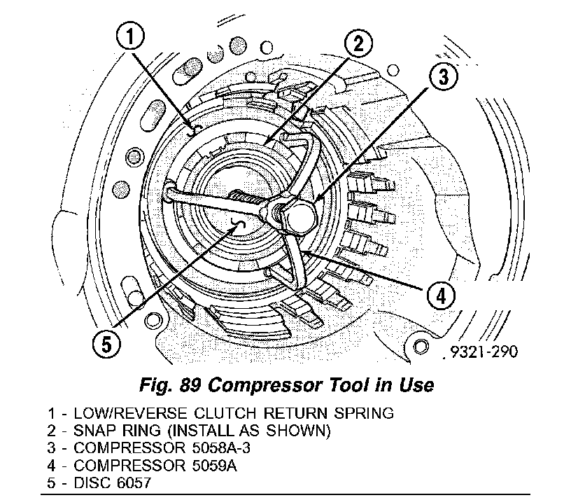
10. Install and load low/reverse spring compressor tool as shown in (Fig. 88) (Fig. 89) to facilitate snap ring installation.
Fig. 90 Install Snap Ring:
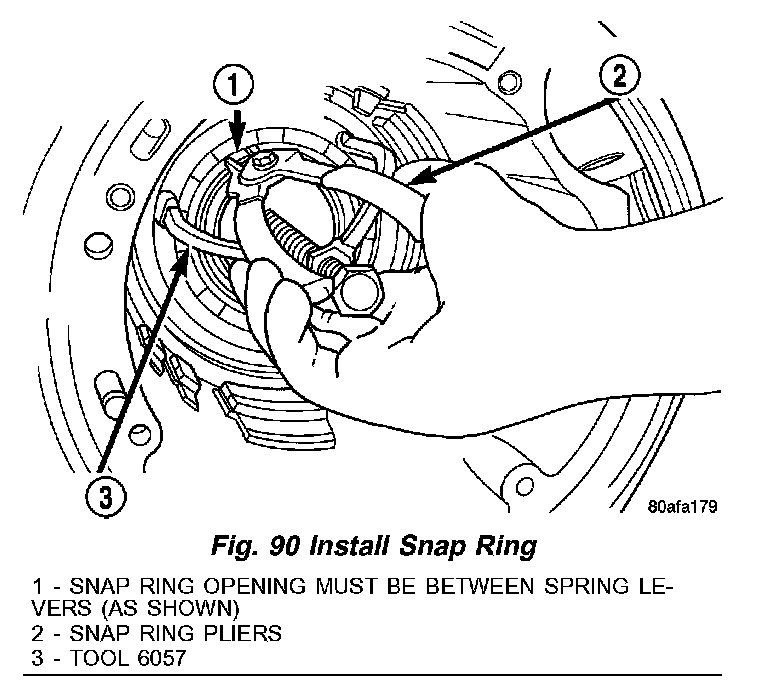
11. Install snap ring and remove compressor tool (Fig. 90).
Fig. 91 Install Rear Carrier Front Bearing Cone:
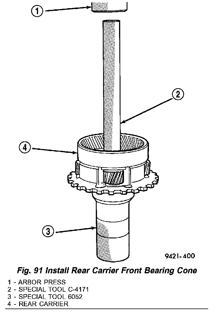
12. Install rear carrier front bearing cone (Fig. 91).
13. Check output bearing preload. Output bearing preload must be checked and/or adjusted if any of the following items have been replaced:
- Output shaft (rear carrier assembly)
- Output shaft bearings
- Transmission case
Fig. 92 Bearing Installation:
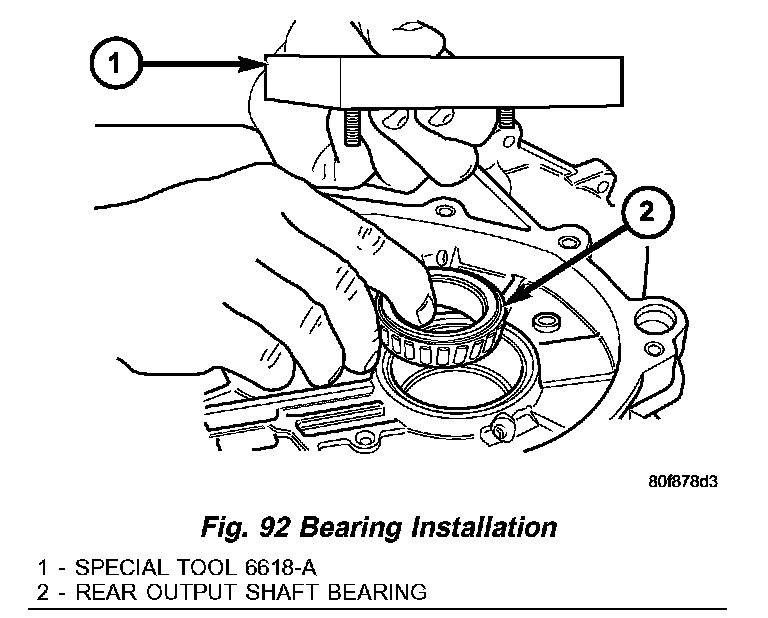
a. PRELOAD CHECK/SHIM SELECTION: Install rear output shaft bearing cone and special tool 6618A (Fig. 92).
Fig. 93 Special Tool Installed:
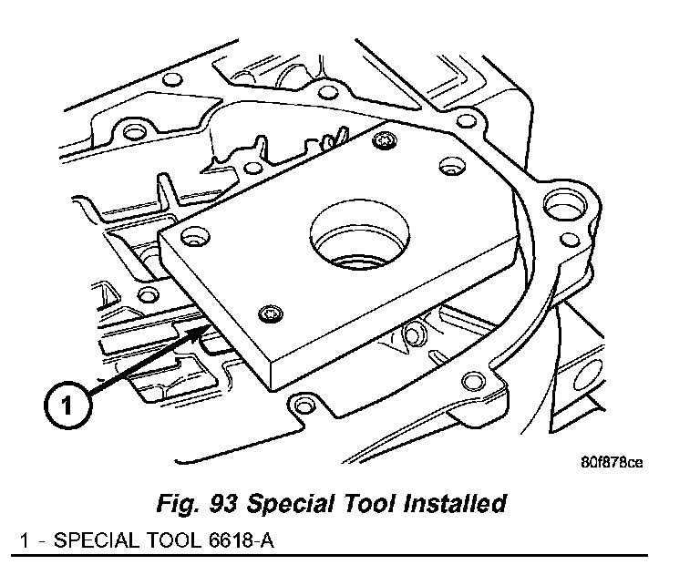
b. Install special tool 6618A (Fig. 93). Lightly tighten retaining screws. Screws should be below the plate surface, but do not snug screws.
c. Turn case over on arbor press so that the plate is resting on the press base.
CAUTION: The output shaft will extend through the hole of tool 6618A. Ensure your press table has clearance for the output shaft.
Fig. 94 Shim Installation:
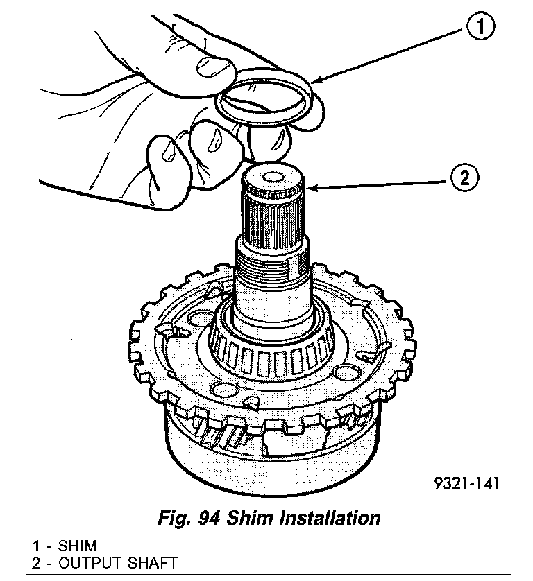
d. Install shim on output shaft (Fig. 94). Apply small amount of petrolatum onto the shim to hold it in place. Use the original shim as a starting point. If original shim is not available, use the thickest shim available.
Fig. 95 Press Shaft Into Case:
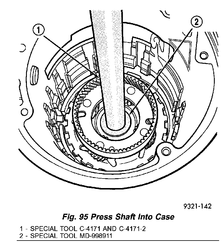
e. Install output shaft/rear carrier into rear bearing. The shaft must be pressed into position. Use special tool MD-998911 (Disc) and C- 4171 and C4171-2 (Handle) to press shaft into rear bearing (Fig. 95).
f. Do not re-use old output shaft nut because the removed stake weakens the nut flange. Using special tools 6497 and 6498-A, install new output shaft nut. Do not reuse old output shaft nut. Tighten new output shaft nut to 271 Nm (200 ft. lbs.).
Fig. 96 Checking Turning Torque:
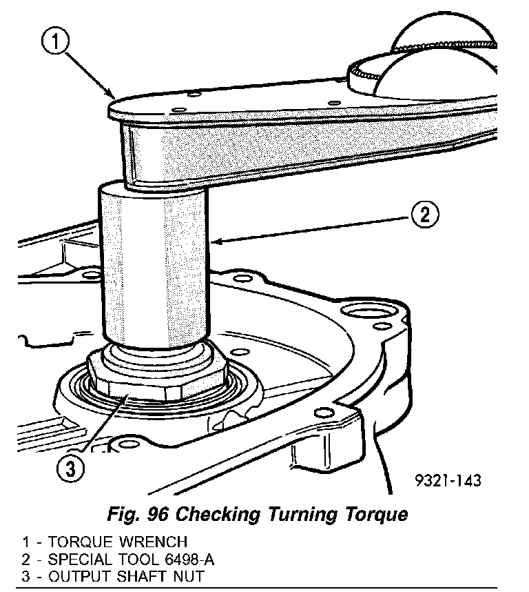
g. Check the turning torque of the output shaft (Fig. 96). The shaft should have 1 to 8 inch lbs. of turning torque. If the turning torque is higher than 8 inch lbs., install a thicker shim. If turning torque is less than 1 inch lb., install a thinner shim. Make sure there is no end play.
Fig. 97 Staking Output Shaft Nut - Typical:
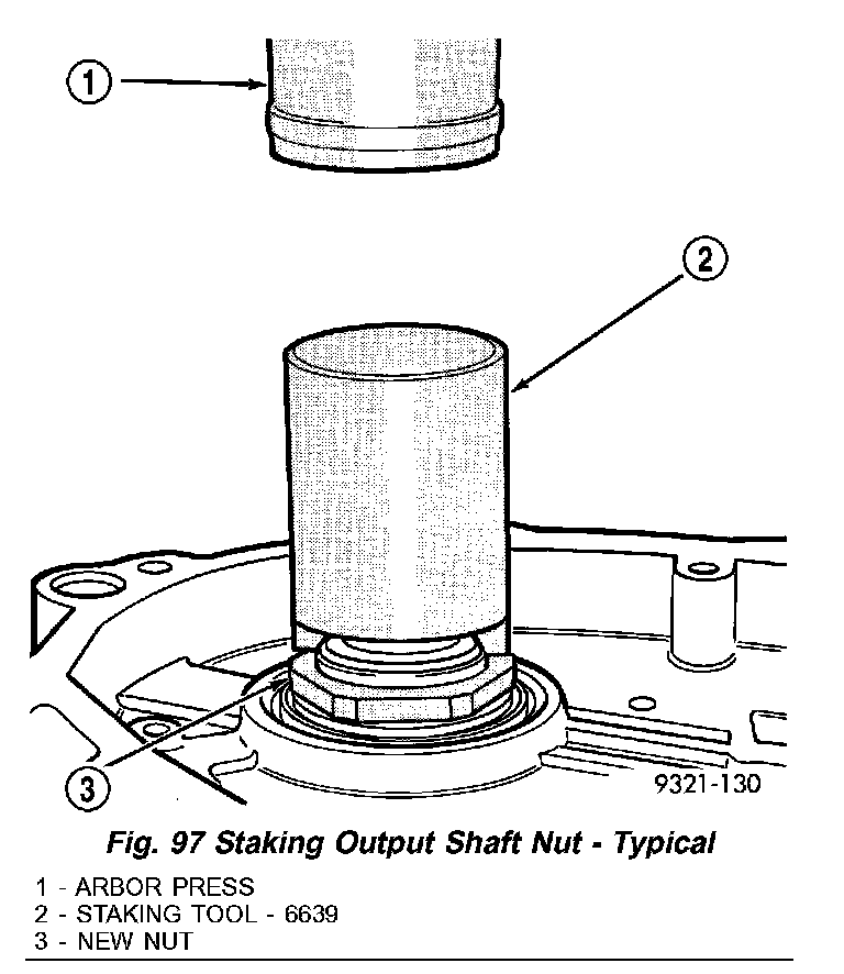
Fig. 98 Properly Staked Nut:
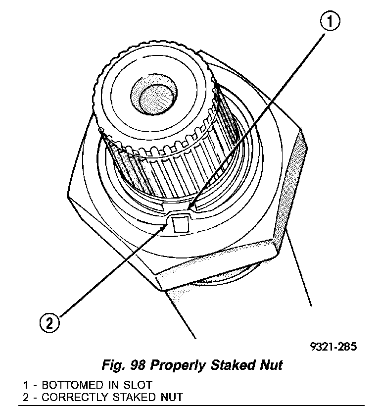
h. The new nut must be staked after the correct turning torque is obtained (Fig. 97) (Fig. 98). Use special tool 6639 to stake output shaft nut.
CAUTION: Failure to stake nut could allow the nut to back-off during use.
Fig. 99 Install Low/Reverse Clutch Pack:
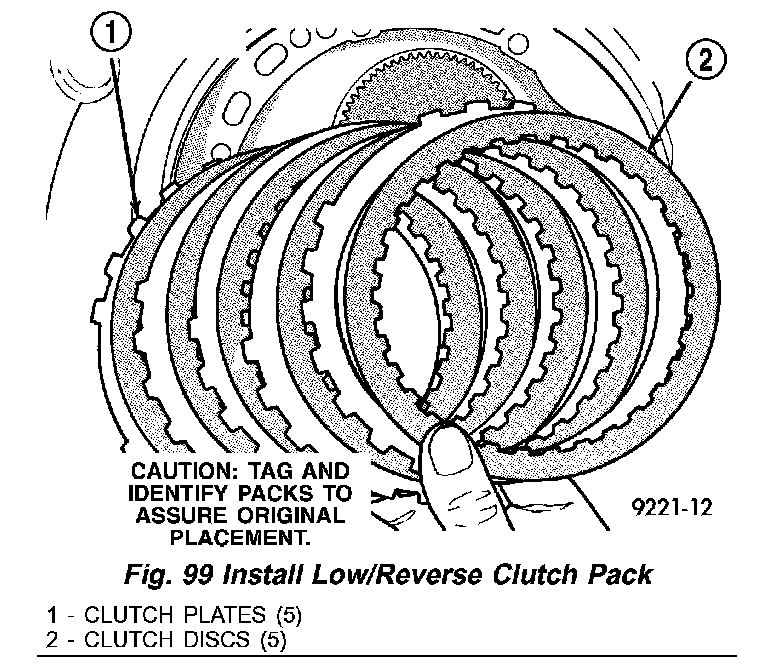
14. Install low/reverse clutch pack (Fig. 99). Leave uppermost disc out to facilitate snap ring installation.
Fig. 100 Install Low/Reverse Reaction Plate Snap Ring:
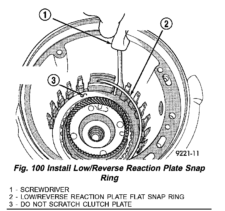
15. Install low/reverse reaction plate snap ring (Fig. 100).
Fig. 101 Install One Disc:
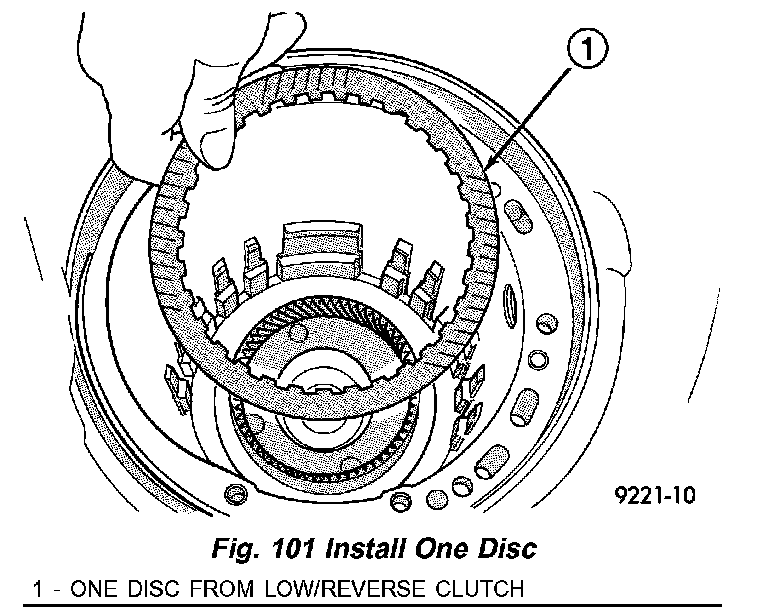
16. Install one low/reverse clutch disc (Fig. 101).
Fig. 102 Install Low/Reverse Reaction Plate:
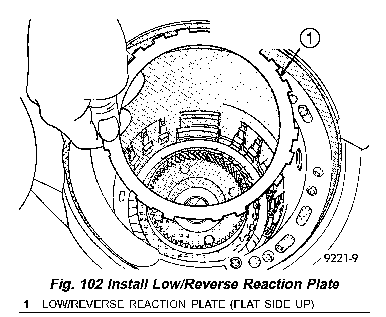
17. Install low/reverse reaction plate with flat side up (Fig. 102).
Fig. 103 Snap Ring Installed:
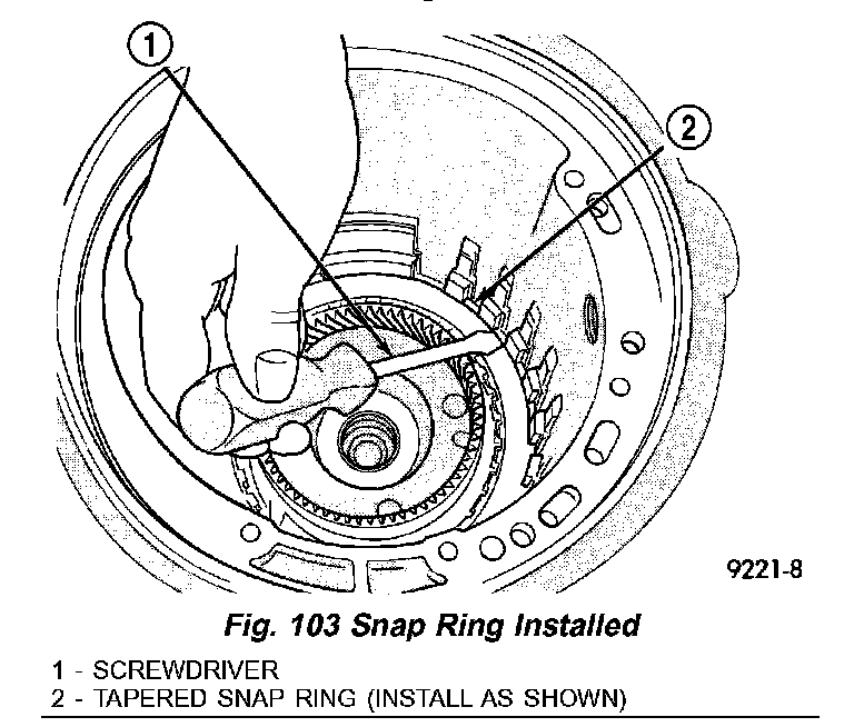
Fig. 104 Tapered Snap Ring Instructions:
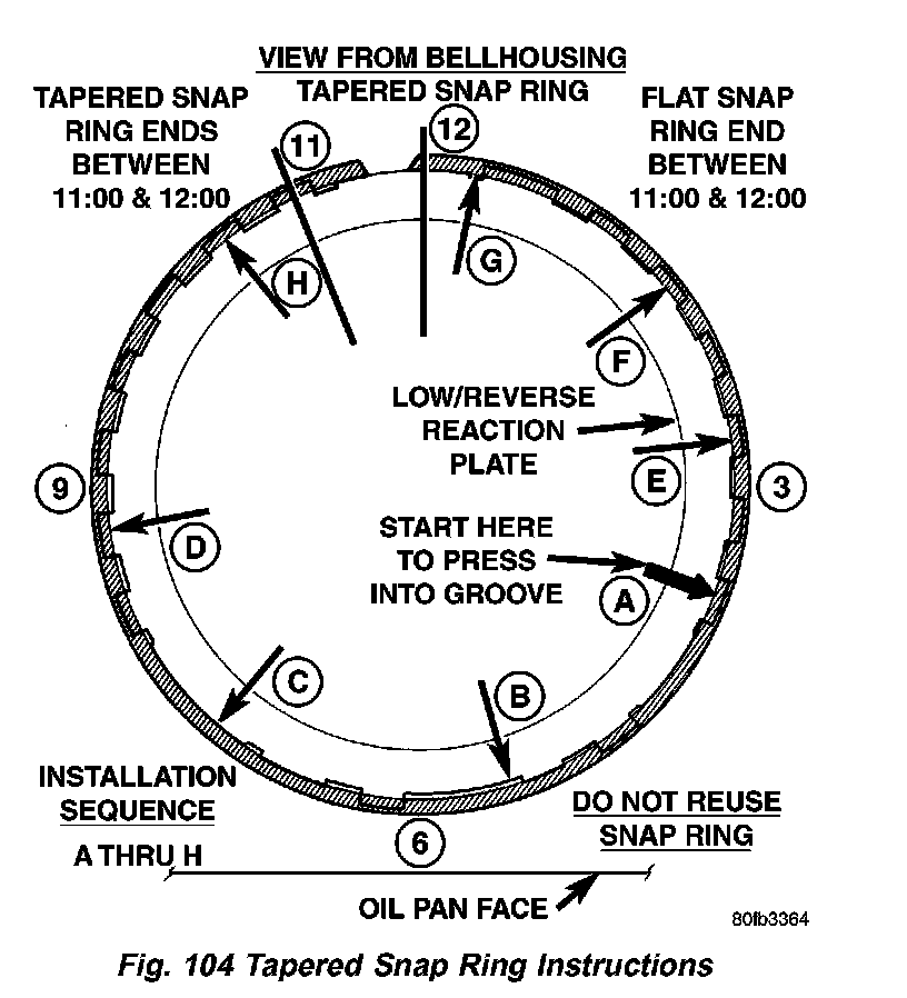
18. Install a new tapered snap ring (tapered side out) (Fig. 103). Make sure that the snap ring ends are oriented as shown (Fig. 104)
Fig. 105 Check Low/Reverse Clutch Clearance:
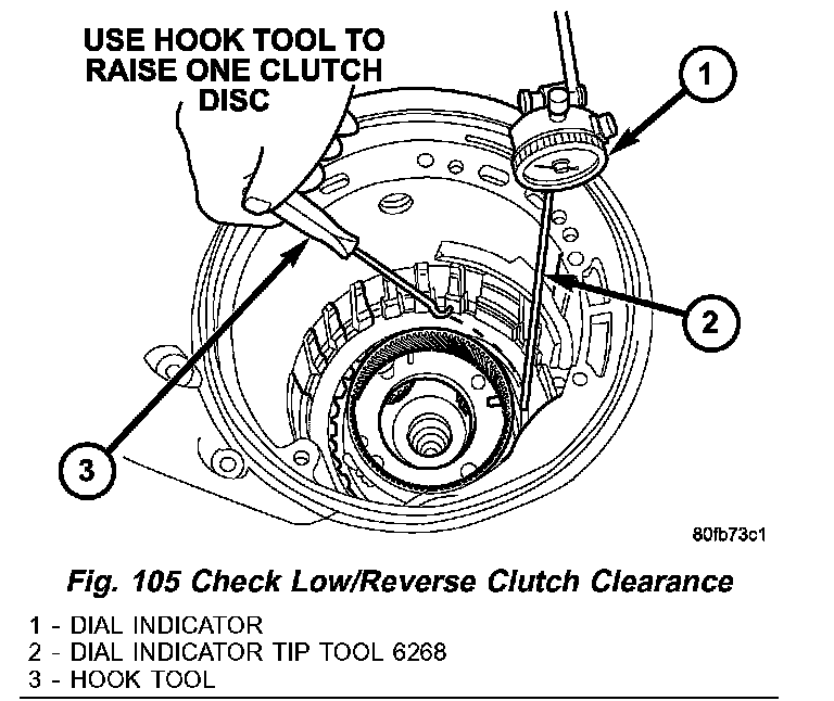
19. Measure low/reverse clutch pack. Set up dial indicator as shown in (Fig. 105). Press down clutch pack with finger and zero dial indicator. Record measurement in four (4) places and take average reading. Low/Reverse clutch pack clearance is 0.84 to 1.60 mm (0.033 to 0.063 inch).
20. Select the proper low/reverse reaction plate to achieve specifications.
Fig. 106 Install 2/4 Clutch Pack:
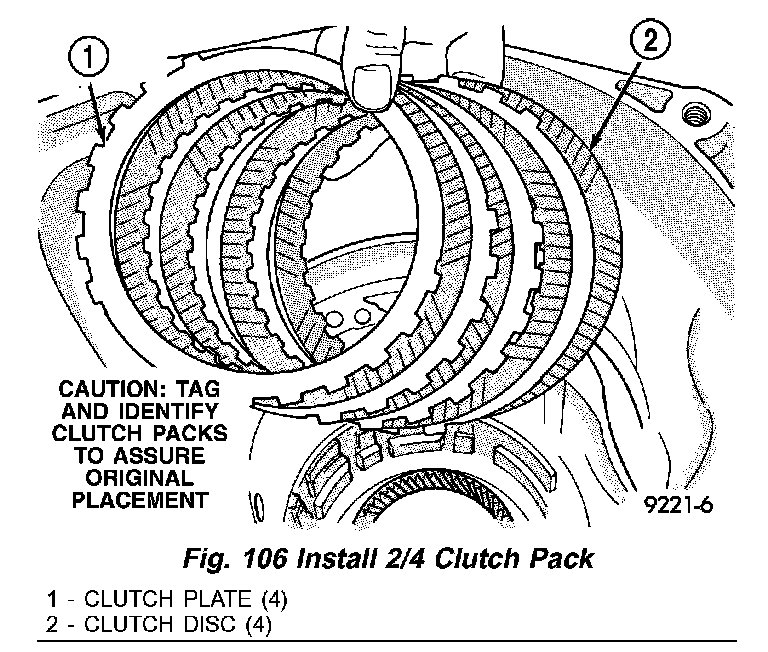
21. Install 2/4 clutch pack (Fig. 106).
NOTE: The 2/4 Clutch Piston has bonded seals which are not individually serviceable. Seal replacement requires replacement of the piston assembly.
Fig. 107 Install 2/4 Clutch Return Spring:
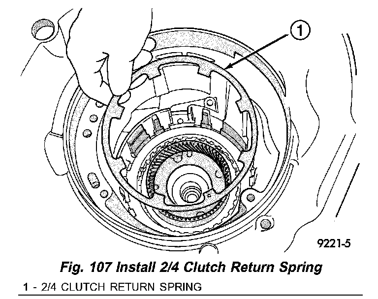
Fig. 108 Proper Orientation of 2/4 Clutch:
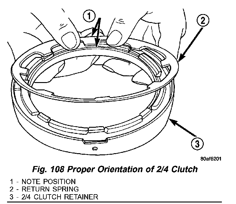
22. Install 2/4 clutch Belleville spring (Fig. 107) (Fig. 108).
Fig. 109 Install 2/4 Clutch Retainer:
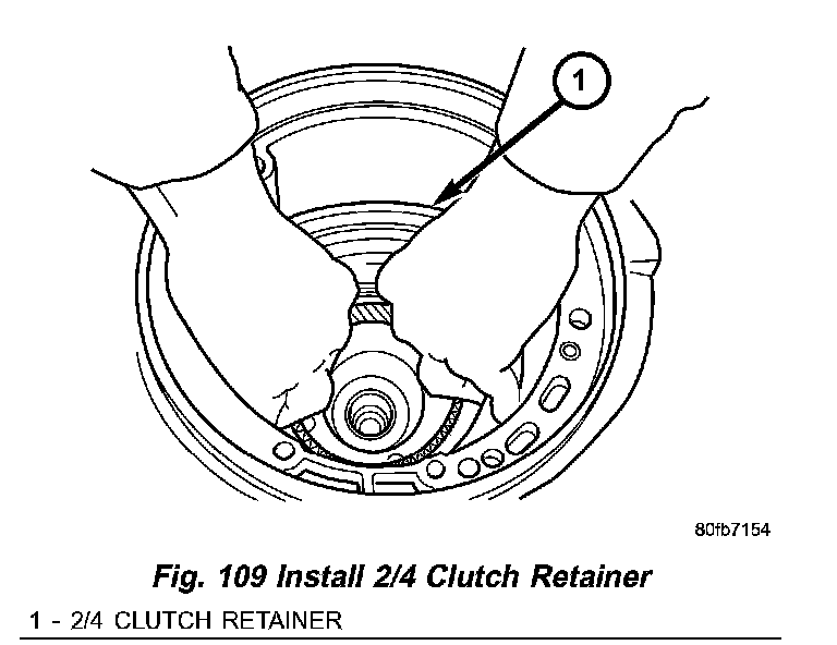
23. Install 2/4 clutch retainer (Fig. 109).
NOTE: Verify that Tool 5058A is centered properly over the 2/4 clutch retainer before compressing. If necessary, fasten the 5058A bar to the bellhousing flange with any combination of locking pliers and bolts to center the tool properly.
Fig. 110 Remove 2/4 Clutch Retainer Snap Ring:
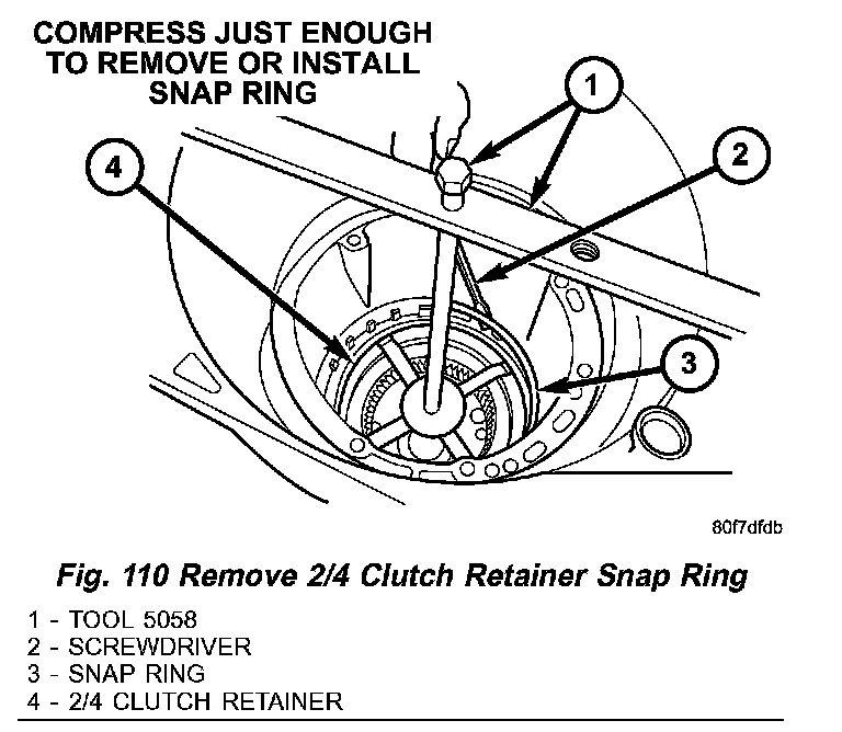
24. Set up Tool 5058 as shown in (Fig. 110). Compress 2/4 clutch just enough to facilitate snap ring installation.
Fig. 111 Check 2/4 Clutch Clearance:
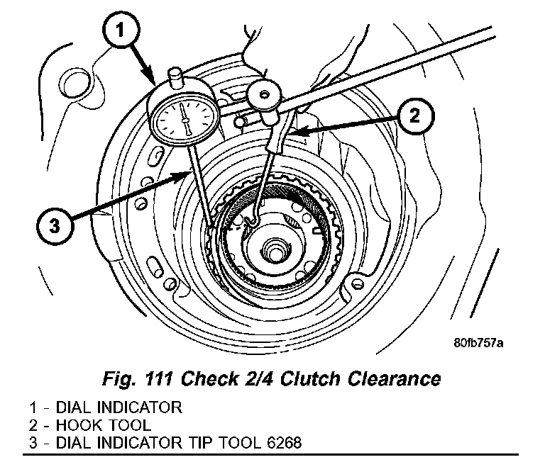
25. Measure 2/4 clutch clearance: Set up dial indicator as shown in (Fig. 111). Press down clutch pack with finger and zero dial indicator. Record measurement in four (4) places and take average reading. The 2/4 clutch pack clearance is 0.76 to 2.64 mm (0.030 to 0.104 inch). If not within specifications, the clutch is not assembled properly or is excessively worn. There is no adjustment for the 2/4 clutch clearance.
Fig. 112 Number 7 Bearing:
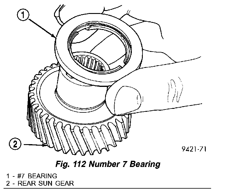
26. Install the #7 needle bearing to the rear sun gear (Fig. 112). The number 7 needle bearing has three antireversal tabs and is common with the number 5 and number 2 position. The orientation should allow the bearing to seat flat against the rear sun gear. A small amount of petrolatum can be used to hold the bearing to the rear sun gear.
Fig. 113 Install Rear Sun Gear:
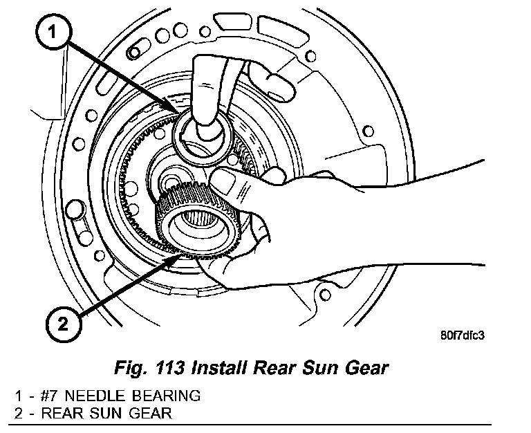
27. Install rear sun gear and #7 needle bearing (Fig. 113).
Fig. 114 Install Front Carrier/Rear Annulus:
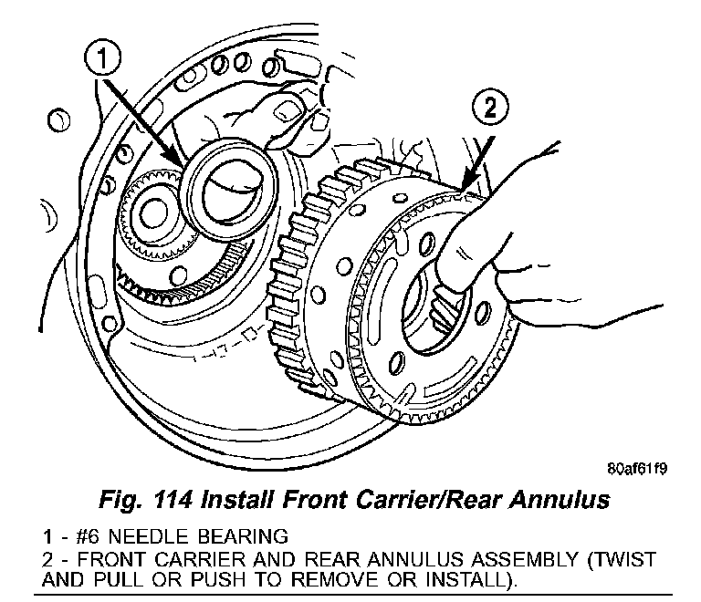
28. Install front carrier/rear annulus assembly and #6 needle bearing (Fig. 114).
Fig. 115 Install Front Sun Gear Assembly:
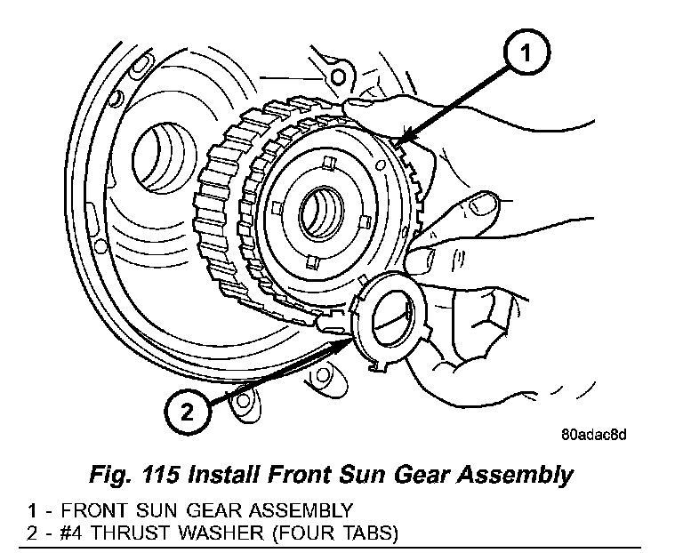
29. Install front sun gear assembly and #4 thrust washer (Fig. 115).
30. Determine proper #4 thrust plate thickness.
a. Select the thinnest #4 thrust plate thickness.
Fig. 116 Install #4 Thrust Plate:
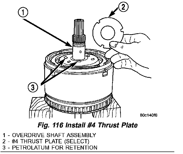
b. Install #4 thrust plate (Fig. 116) using petrolatum to hold into position.
c. Install input clutch assembly. Ensure the input clutch assembly is completely seated by viewing position through input speed sensor hole. If the speed sensor tone wheel is not centered in the opening, the input clutch assembly is not seated properly.
Fig. 117 Remove Oil Pump O-Ring:
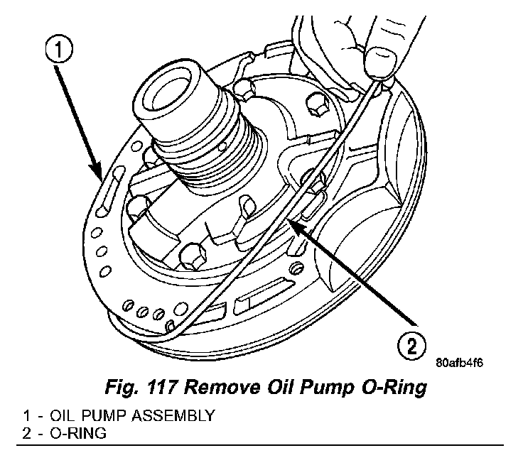
d. Remove the oil pump O-ring (Fig. 117) and install oil pump and gasket to transmission. Tighten the oil pump bolts to 30 Nm (265 inch lbs.). Use screw-in dowels or phillips-head screwdrivers to align pump to case. Be sure to reinstall O-ring on oil pump after selecting the proper No. 4 thrust plate.
e. Measure the input shaft end play with the transmission in the vertical position. This will ensure that the measurement will be accurate.
Fig. 118 Measure Input Shaft End Play Using Tool 8266 - Typical:
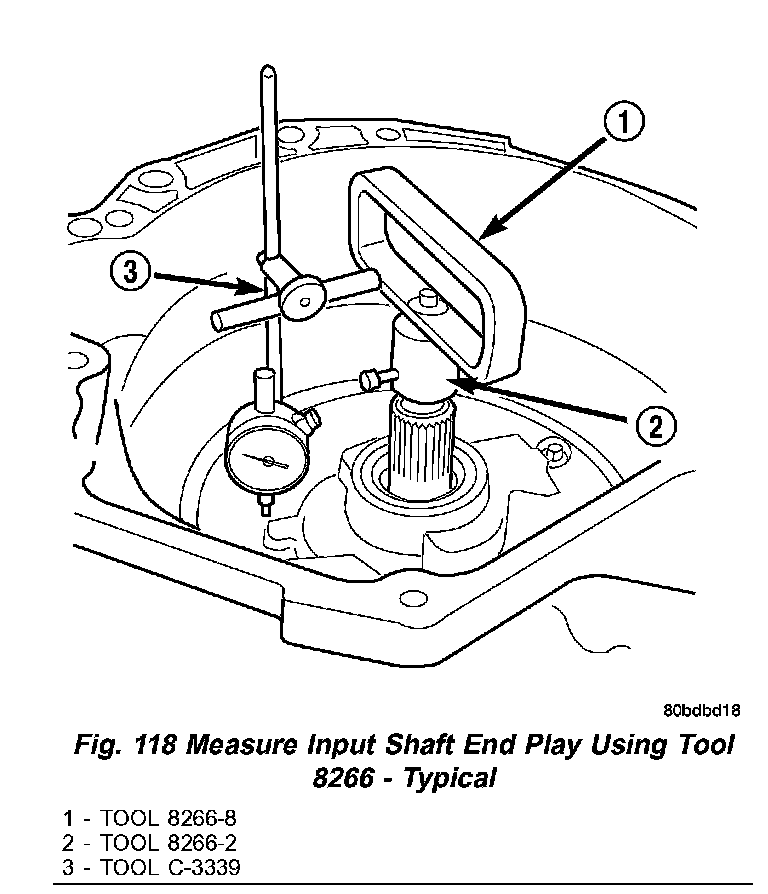
f. Set up and measure endplay using End Play Set 8266 and Dial Indicator Set C3339 as shown in (Fig. 118).
g. Measure input shaft end play. Input shaft end play must be 0.127 to 0.635 mm (0.005 to 0.025 inch). For example, if end play reading is 0.055 inch, select No. 4 Thrust Plate which is 0.071 to 0.074 thick. This should provide an input shaft end play reading of 0.020 inch, which is within specifications.
h. Remove oil pump, gasket, and input clutch assembly to gain access to and install proper #4 thrust plate.
Fig. 119 Install Input Clutch Assembly:
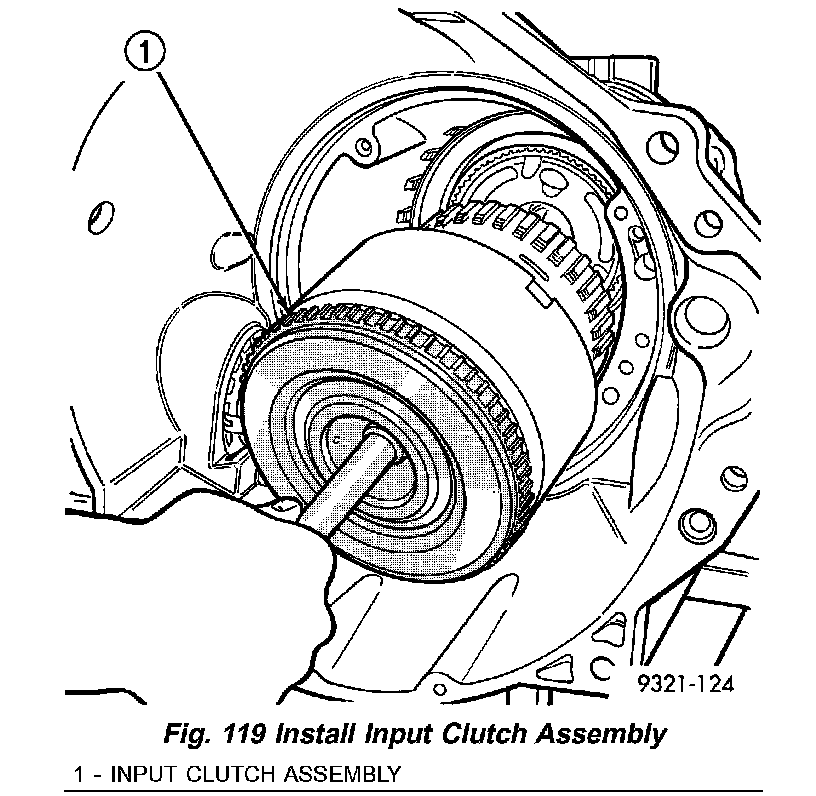
31. Install input clutch assembly with proper thrust plate (Fig. 119).
Fig. 120 Install No. 1 Caged Needle Bearing:
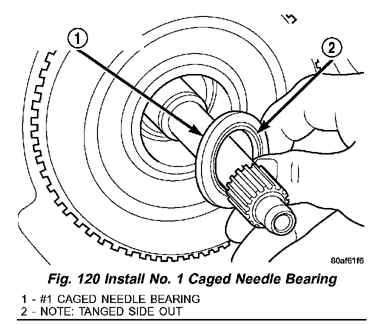
32. Install #1 caged needle bearing (Fig. 120).
Fig. 121 Install By-Pass Valve:
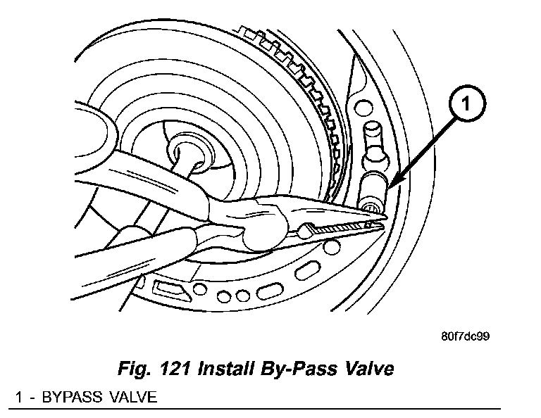
33. Replace cooler by-pass valve if transmission failure has occurred (Fig. 121).
CAUTION: By-pass valve MUST be replaced if transmission failure occurs.
NOTE: To align oil pump, gasket, and case during installation, use threaded dowels or phillips screwdrivers.
Fig. 122 Install Oil Pump Gasket:
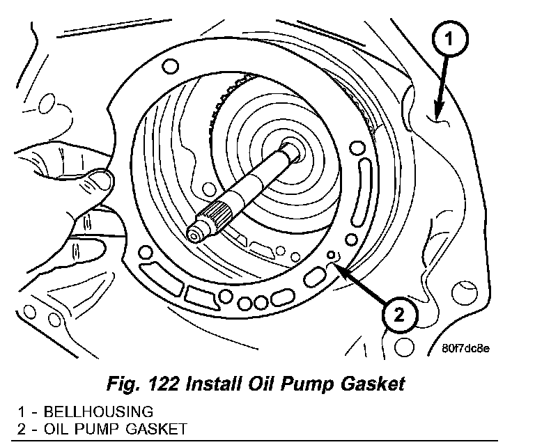
34. Install oil pump gasket (Fig. 122).
Fig. 123 Install Oil Pump Attaching Bolts:
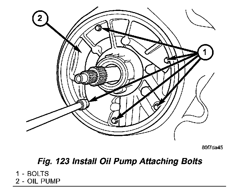
35. Install oil pump and torque the new oil pump-to-case bolts to 30 Nm (265 inch lbs.)(Fig. 123). Do not reuse original oil pump bolts.
Fig. 124 Low/Reverse Accumulator:
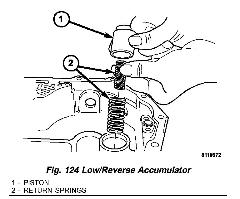
36. Install low/reverse accumulator as shown in (Fig. 124).
Fig. 125 Install Low/Reverse Accumulator Plug:
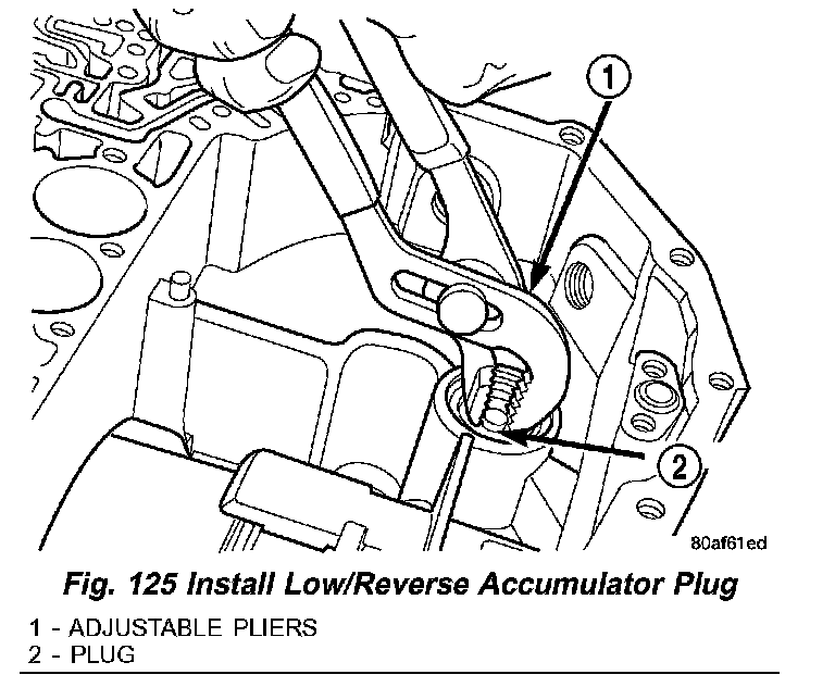
37. Install low/reverse accumulator plug (Fig. 125).
Fig. 126 Install Low/Reverse Accumulator Snap Ring:
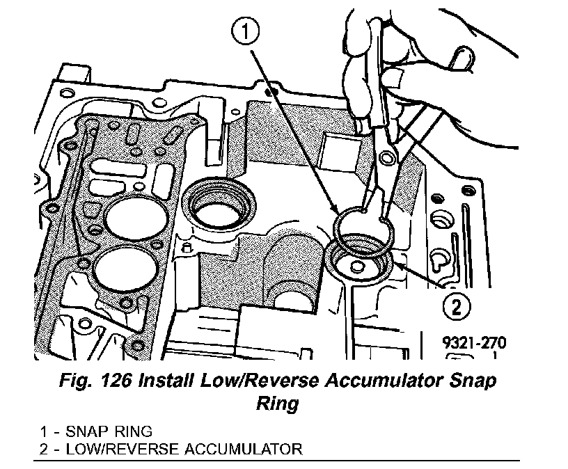
38. Install low/reverse accumulator snap ring (Fig. 126).
Fig. 127 Underdrive and Overdrive Accumulators:
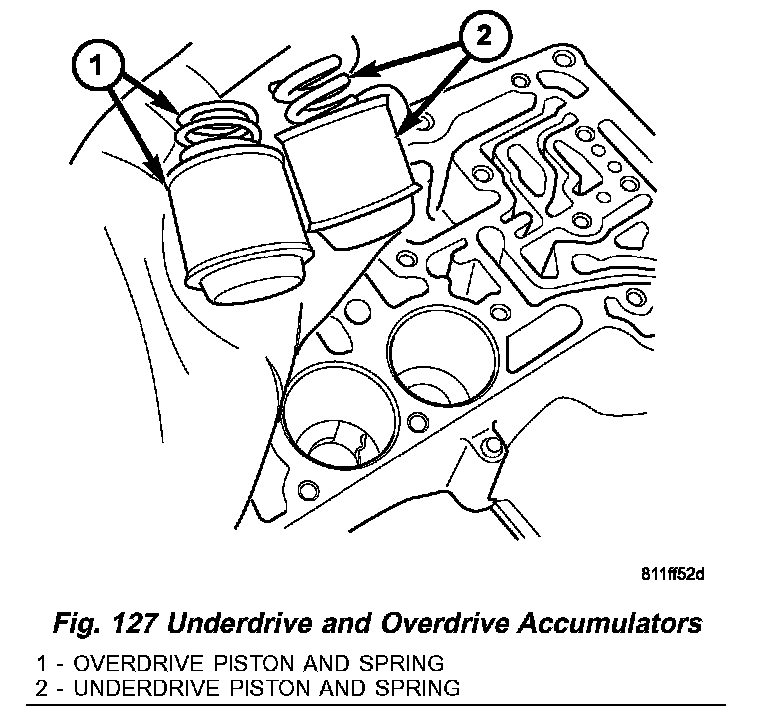
39. Install underdrive and overdrive accumulators and springs (Fig. 127).
CAUTION: Do not handle the valve body by the manual shaft. Damage could result.
Fig. 128 Install Valve Body Onto Transmission:
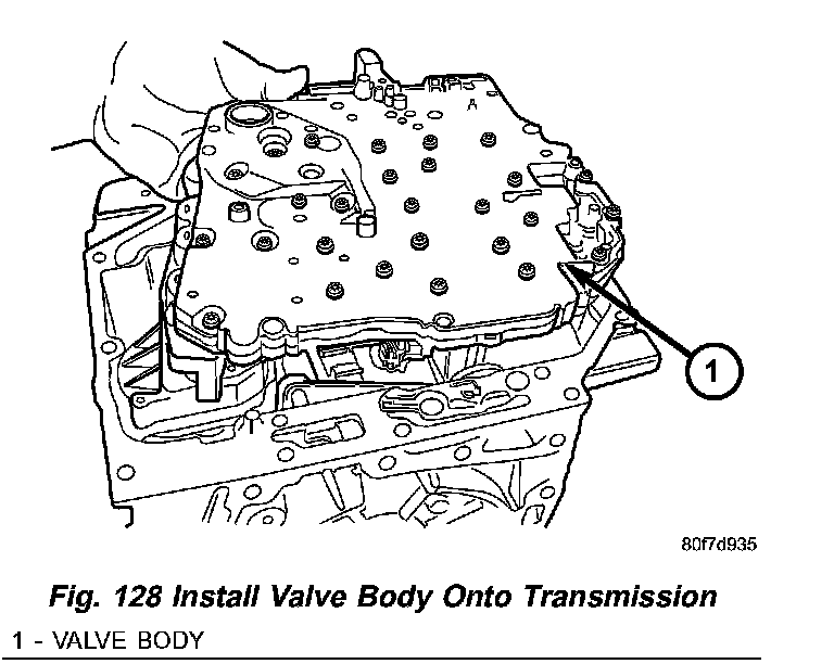
40. Install valve body into place as shown in (Fig. 128).
Fig. 129 Install Valve Body Bolts (7):
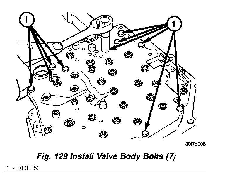
41. Install seven (7) valve body-to-case bolts (Fig. 129) and torque to 12 Nm (105 inch lbs.).
Fig. 130 Install Transmission Filter:
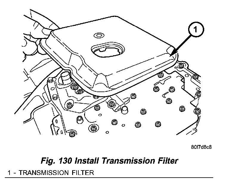
42. Install transmission oil filter (Fig. 130). Tighten the bolts to 5 Nm (45 inch lbs.)
Fig. 131 Pan Fastener:
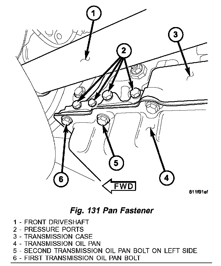
NOTE: Before installing the oil pan bolt in the bolt hole located between the torque converter clutch on and U/D clutch pressure tap circuits (Fig. 131), it will be necessary to replenish the sealing patch on the bolt using Mopar Lock & Seal Adhesive.
Fig. 132 Install Transmission Oil Pan:
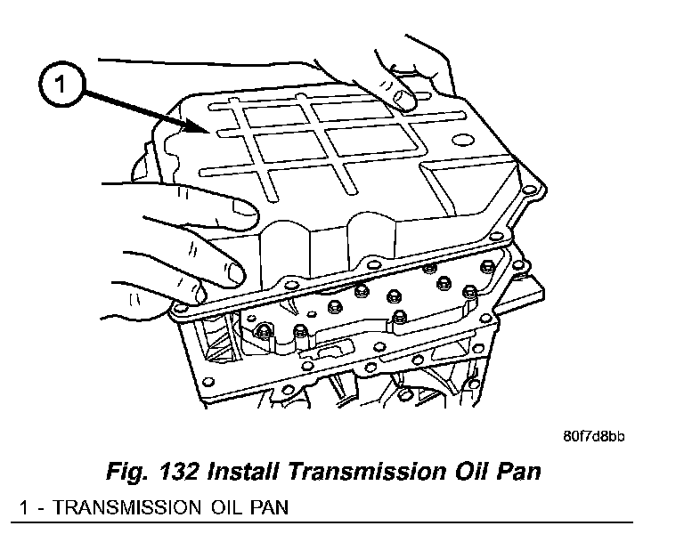
43. Install transmission oil pan (Fig. 132) with a bead of Mopar ATF RTV. Torque oil pan-to-case bolts to 20 Nm (14.5 ft. lbs.).
NOTE: Before installing either speed sensor bolt, it will be necessary to replenish the sealing patch on the bolt using Mopar Lock & Seal Adhesive.
Fig. 133 Input and Output Speed Sensors and Transmission Range Sensor:
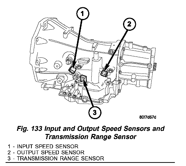
44. Install both speed sensors into transmission case (Fig. 133). Torque the speed sensor bolts to 9 Nm (80 inch lbs.).
Fig. 134 Measure Input Shaft End Play Using Tool 8266 - Typical:
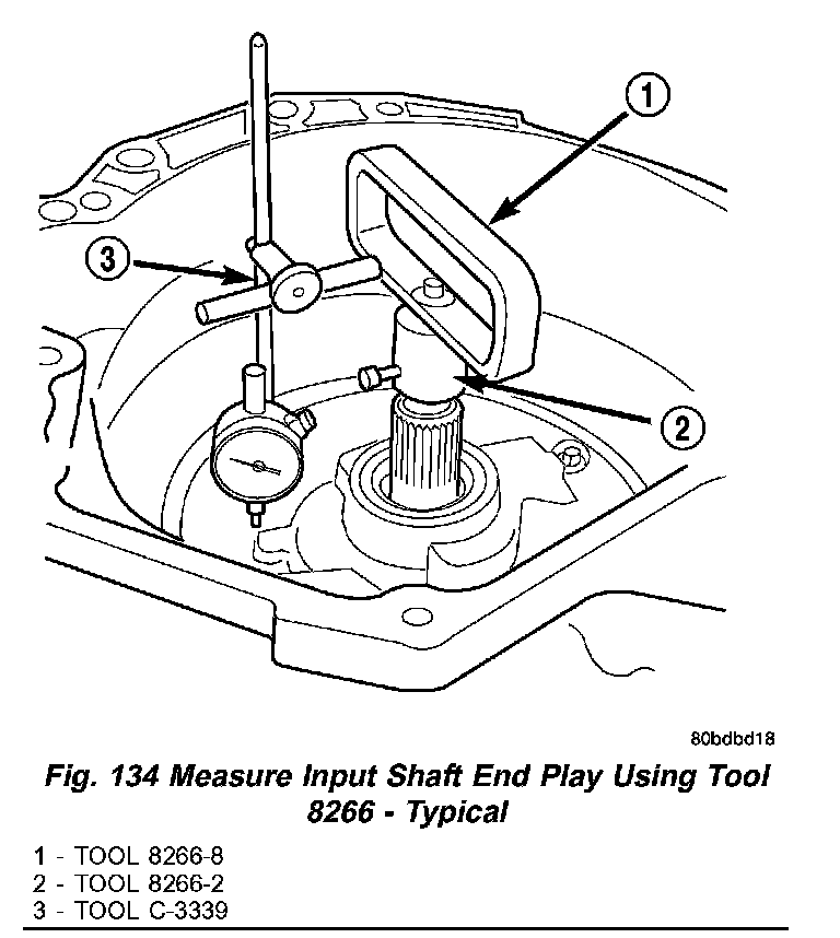
45. As a final check of the transmission, measure the input shaft end play. This will indicate when a #4 thrust plate change is required. The #4 thrust plate is located behind the overdrive clutch hub. Attach a dial indicator to transmission bell housing with its plunger seated against end of input shaft (Fig. 134). Move input shaft in and out to obtain end play reading. Input shaft end play must be 0.127 to 0.635 mm (0.005 to 0.025 inch). If not within specifications, make the necessary thrust plate adjustment.
Fig. 135 Lube Tube Grommet:
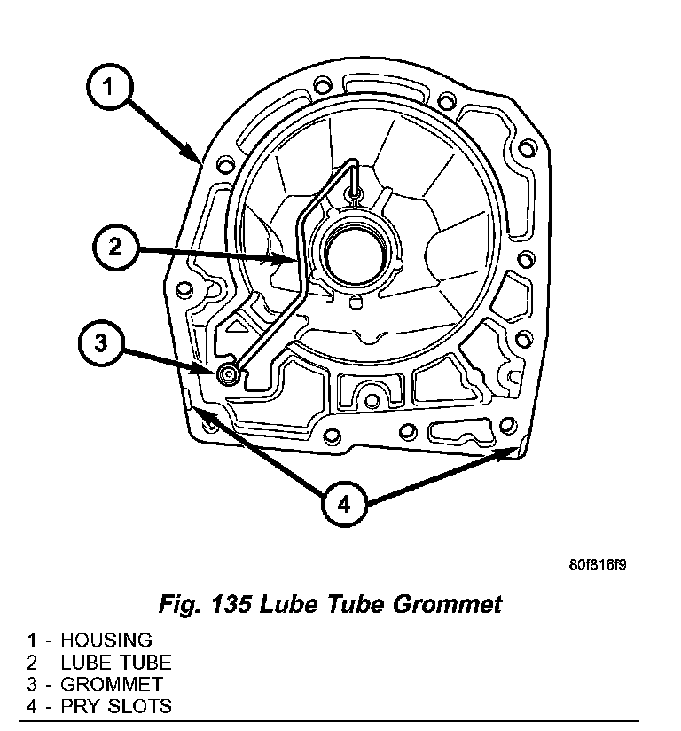
46. Inspect the lube tube grommet (Fig. 135) for damage. If the grommet lip is damaged, it will need to be replaced.
47. Install the 4X4 stub shaft onto the transmission output shaft.
48. Place a bead of Mopar ATF RTV on the rear surface of the transmission case for the adapter housing.
Fig. 136 Install Adapter Housing:
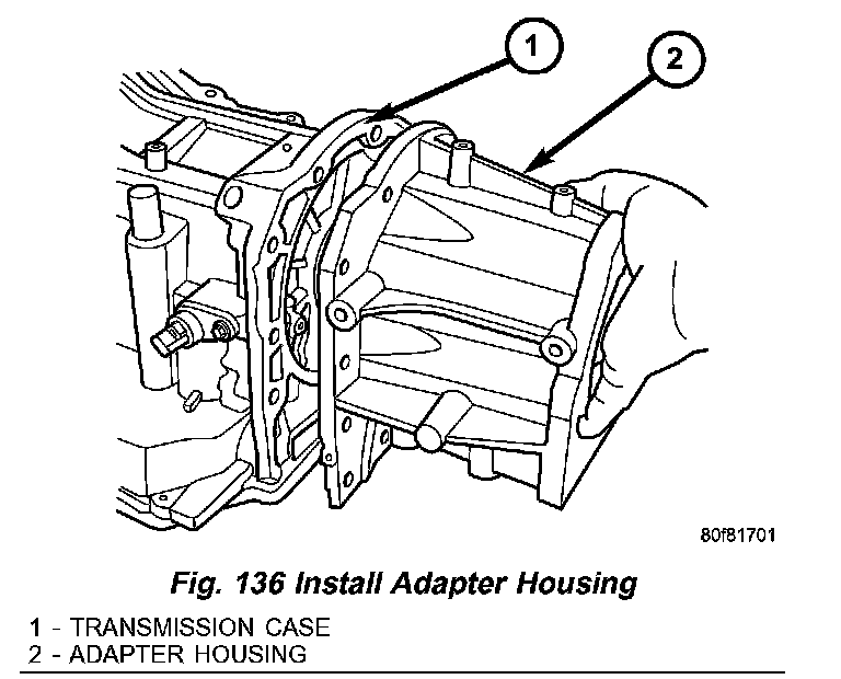
49. Install the adapter (Fig. 136) housing onto the transmission case.
Fig. 137 Adapter Housing Fasteners:
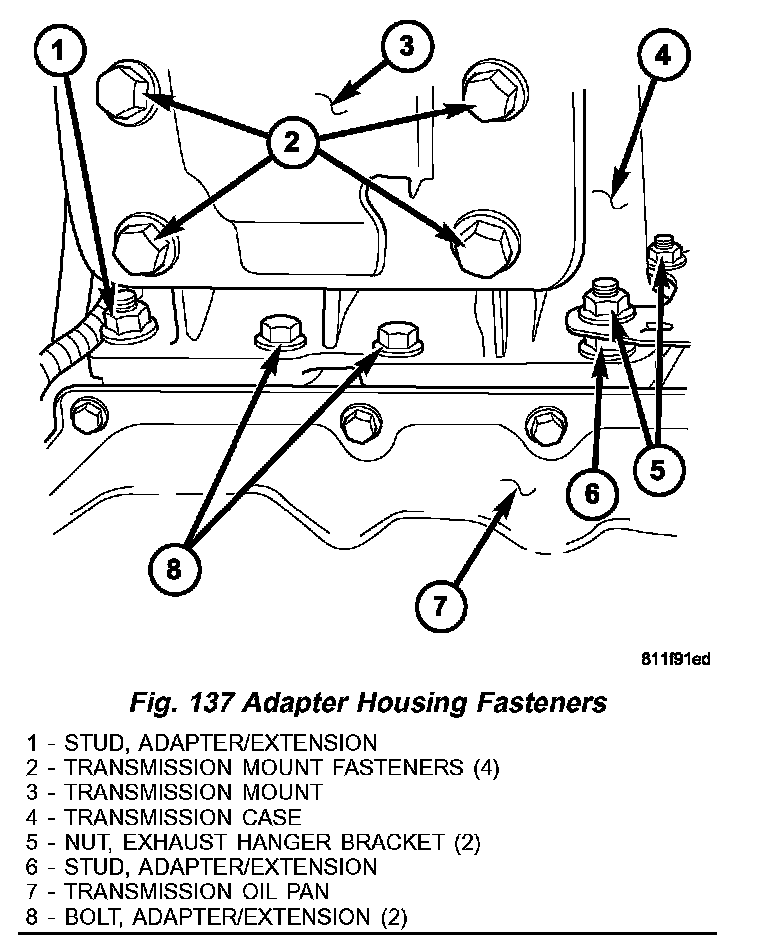
NOTE: Before installing the lowermost four adapter housing bolts (Fig. 137), it will be necessary to replenish the sealing patch on the bolts using Mopar Lock & Seal Adhesive.
Fig. 138 Install Adapter Housing Bolts:
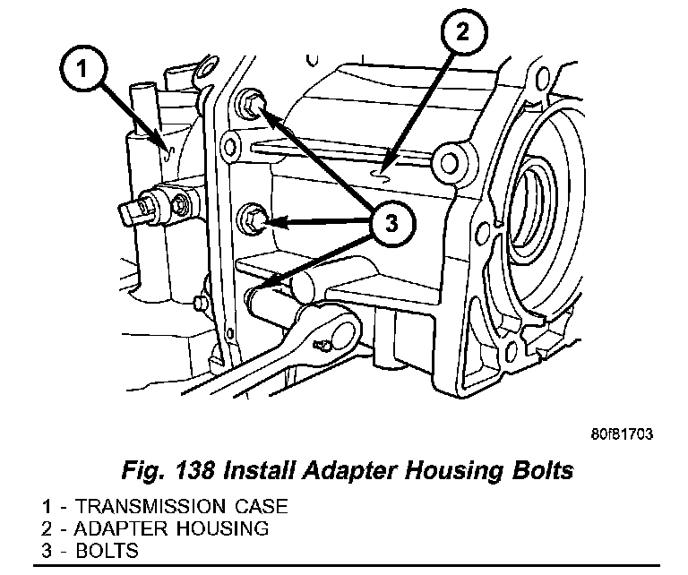
50. Install the bolts (Fig. 138) that hold the adapter housing onto the transmission case. Be sure to install any stud bolts to their original locations. Tighten the bolts to 54 Nm (40 ft. lbs.).