Part 2
ASSEMBLY (Continued)
24. Install low/reverse reaction plate (1) with flat side up.


25. Install a new tapered snap ring (2) (tapered side out).

26. Make sure that the snap ring ends are oriented as shown.

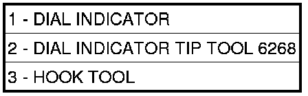
27. Measure low/reverse clutch pack. Set up dial indicator (1) as shown. Press down clutch pack with finger and zero dial indicator. Record measurement in four (4) places and take average reading. Low/Reverse clutch pack clearance is 0.84 to 1.60 mm (0.033 to 0.063 inch).
28. Select the proper low/reverse reaction plate to achieve specifications.

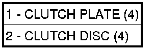
29. Install 2/4 clutch pack (1, 2).


NOTE: The 2/4 Clutch Piston has bonded seals which are not individually serviceable. Seal replacement requires replacement of the piston assembly.
30. Install 2/4 clutch belleville spring (1).

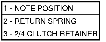
31. Verify the proper orientation of the return spring (2) to the 2/4 retainer (3).


32. Install 2/4 clutch retainer (1).

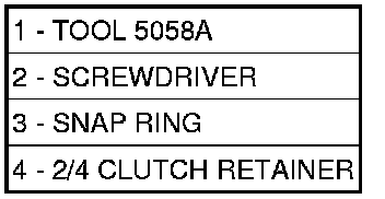
NOTE: Verify that Compressor (1) is centered properly over the 2/4 clutch retainer (4) before compressing. If necessary, fasten the bar from Compressor to the bellhousing flange with any combination of locking pliers and bolts to center the tool properly.
33. Set up Compressor (1) as shown. Compress 2/4 clutch just enough to facilitate snap ring installation.

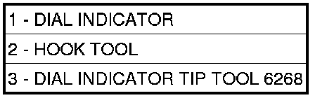
34. Measure 2/4 clutch clearance: Set up dial indicator (1) as shown. Press down clutch pack with finger and zero dial indicator. Record measurement in four (4) places and take average reading. The 2/4 clutch pack clearance is 0.76 to 2.64 mm (0.030 to 0.104 inch). If not within specifications, the clutch is not assembled properly or is excessively worn. There is no adjustment for the 2/4 clutch clearance.

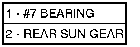
35. Install the #7 needle bearing (1) to the rear sun gear (2). The number 7 needle bearing has three anti-reversal tabs and is common with the number 5 and number 2 position. The orientation should allow the bearing to seat flat against the rear sun gear. A small amount of petrolatum can be used to hold the bearing to the rear sun gear.

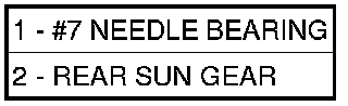
36. Install rear sun gear (2) and #7 needle bearing (1).


37. Install front carrier/rear annulus assembly (2) and #6 needle bearing (1).


38. Install front sun gear assembly (1) and #4 thrust washer (2).

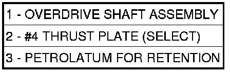
39. Determine proper #4 thrust plate thickness. Select the thinnest available #4 thrust plate.
40. Install #4 thrust plate (2) using petrolatum to hold into position.
41. Install input clutch assembly. Ensure the input clutch assembly is completely seated by viewing position through input speed sensor hole. If the speed sensor tone wheel is not centered in the opening, the input clutches assembly is not seated properly.
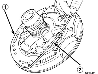
42. Remove the oil pump o-ring (2) and install oil pump and gasket to transmission. Use screw-in dowels or Phillips head screwdrivers to align pump to case. Be sure to reinstall O-ring on oil pump after selecting the proper No. 4 thrust plate.

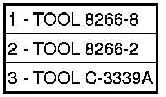
43. Measure the input shaft end play with the transmission in the vertical position. This will ensure that the measurement will be accurate.
44. Set up and measure endplay using End Play Set (1, 2) and Dial Indicator Set (3) as shown.
45. Measure input shaft end play. Input shaft end play must be 0.127 to 0.635 mm (0.005 to 0.025 inch). For example, if end play reading is 0.055 inch, select No. 4 Thrust Plate which is 0.071 to 0.074 thick. This should provide an input shaft end play reading of 0.020 inch, which is within specifications.

