Part 1
ASSEMBLY
Special Tools:
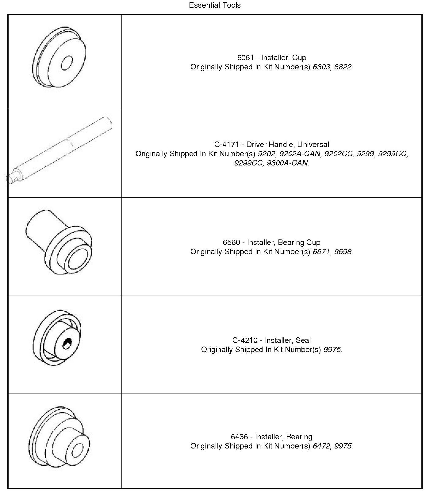
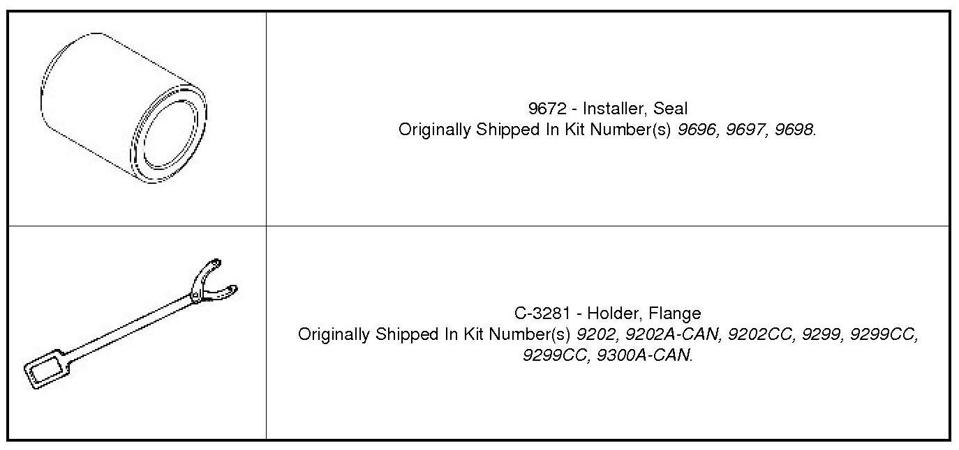
NOTE: Lubricate all seals with MOPAR(R) ATF+4 prior to installation.

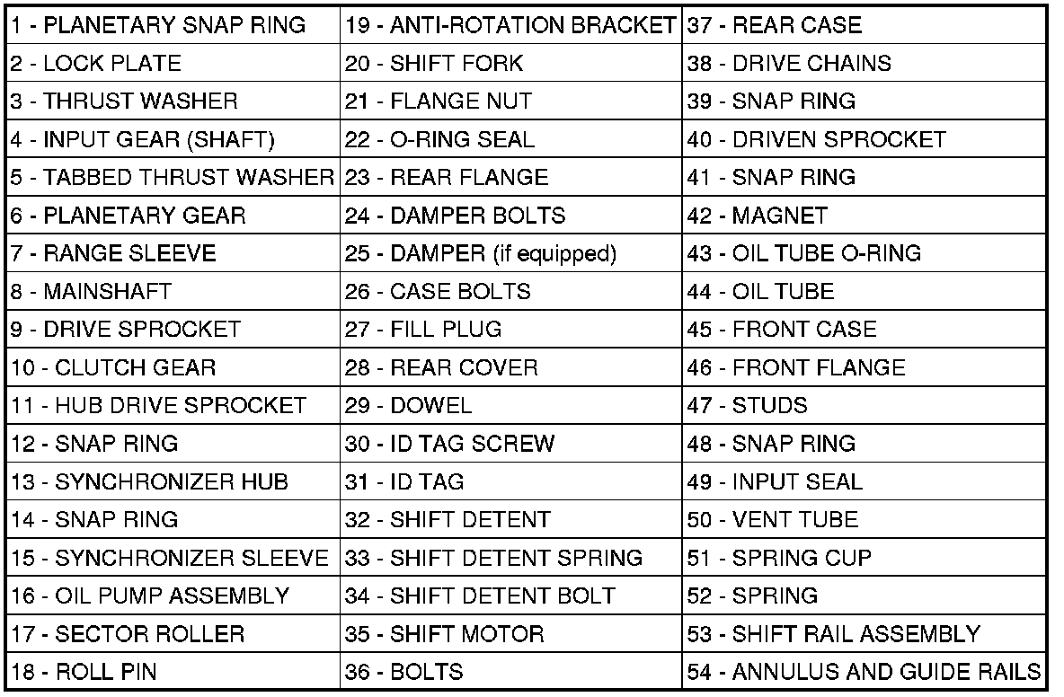
Figure 1 - MP1522 EXPLODED VIEW
CAUTION: The bearing bores in various transfer case components contain oil feed holes. Be certain the holes are not blocked. Failure to follow this caution may result in transfer case damage.
NOTE: Lubricate all seals with MOPAR(R) ATF+4 prior to installation.
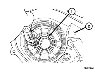
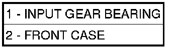
1. While holding the retaining ring tabs apart with suitable snap-ring pliers, remove the input shaft bearing (1) from the front case (2).
2. Transfer the retaining ring to the new housing, if necessary, and install the bearing into the front case.
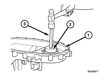
3. Remove the front output shaft seal with a suitable pry tool or a screw mounted in a slide hammer.
4. Using inverted Installer and Handle , remove front output shaft bearing.
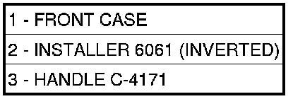
5. Start front output shaft bearing in case. Then seat bearing with Handle (3) and inverted Installer (2).
6. Using Handle (1) and Installer (2) install the front output shaft seal (3).
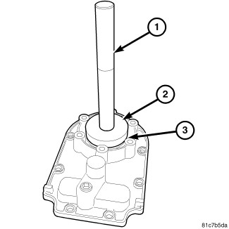
Figure 4 - REAR OUTPUT SHAFT SEAL
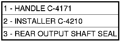
7. Remove the rear output shaft seal with a suitable pry tool or a screw mounted in a slide hammer.
8. Install a new rear output shaft seal (3) into the rear cover using handle (1) and Installer (2).
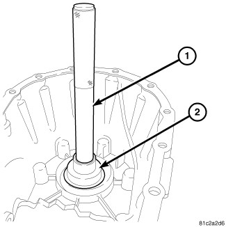
Figure 5 - REMOVE REAR OUTPUT SHAFT BEARING

9. Remove the rear output shaft bearing from the rear case using inverted Installer (2) and Handle (1).
10. Install the rear output shaft bearing into the rear case using inverted Remover/Installer (2) and Handle (1).


NOTE: The tabbed side of the thrust washer faces upward.
11. Install the rear tabbed thrust washer (2) into the planetary gear (1).

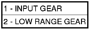
12. Install the input gear (1) into the planetary gear (2).

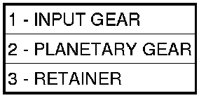
13. Install the input gear lock plate (3) onto the planetary gear (2) and install it into the planetary.


14. Install the snap-ring (1) to hold the input gear into the planetary gear.
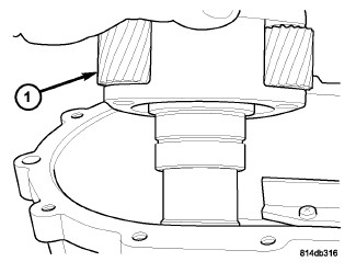

15. Install the input planetary gear assembly (1) into the front housing.

Figure 11 - INPUT GEAR SNAP RING
16. Install the retaining ring (2) holding the input planetary gear assembly into the front housing.
17. Install the new input shaft seal with Installer and Handle.
18. Install a new front output shaft seal with Installer.
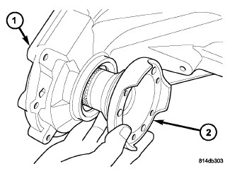
19. Install the front output shaft (2) into the front housing (1) and the front output shaft front bearing.
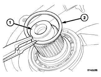
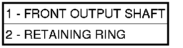
20. Install the retaining ring (2) onto the front output shaft (1).

Figure 14 - SHIFT RAIL SPRING AND SEAT
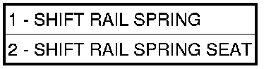
21. Install the shift rail spring cup (2) and shift rail spring (1).

Figure 15 - SHIFT RAIL AND RANGE SLEEVE
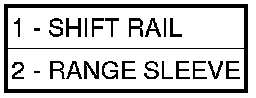
22. Install the shift rail (1) and range sleeve (2).

Figure 16 - MAIN SHAFT

23. Install the mainshaft (1).
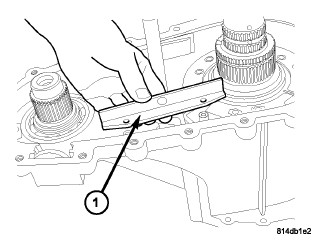

24. Install the both drive chain guides (1) onto the transfer case.
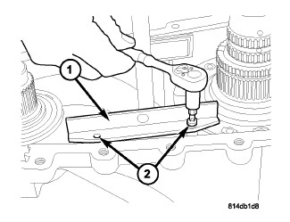
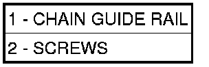
25. Install the screws (2) to hold the chain guide rails (1) to the front housing. Tighten the screws to 5-8 Nm (44-71 in.lbs.).
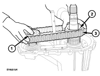
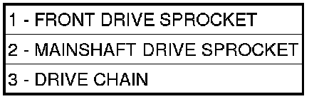
CAUTION: Be careful not to damage the ground surface of the mainshaft while installing the sprockets and drive chain. Failure to follow this caution may result in transfer case damage.