Shift Interlock Solenoid: Service and Repair
1. Disconnect battery ground cable.Fig. 18 Shift Lock Actuator Replacement:
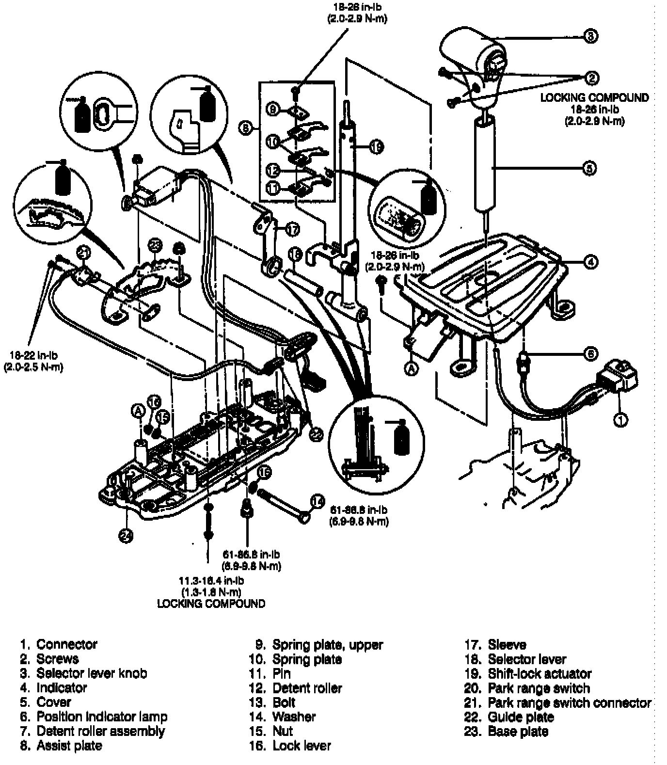
2. Remove components in numerical order as outlined in Fig. 18.

Fig. 20 Shift Lever Guide Plate Clearance Adjustment:
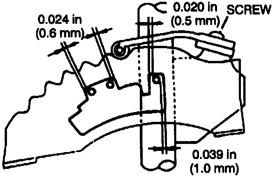
Fig. 21 Shift Indicator Guide Plate And Pin Clearance Dimension:
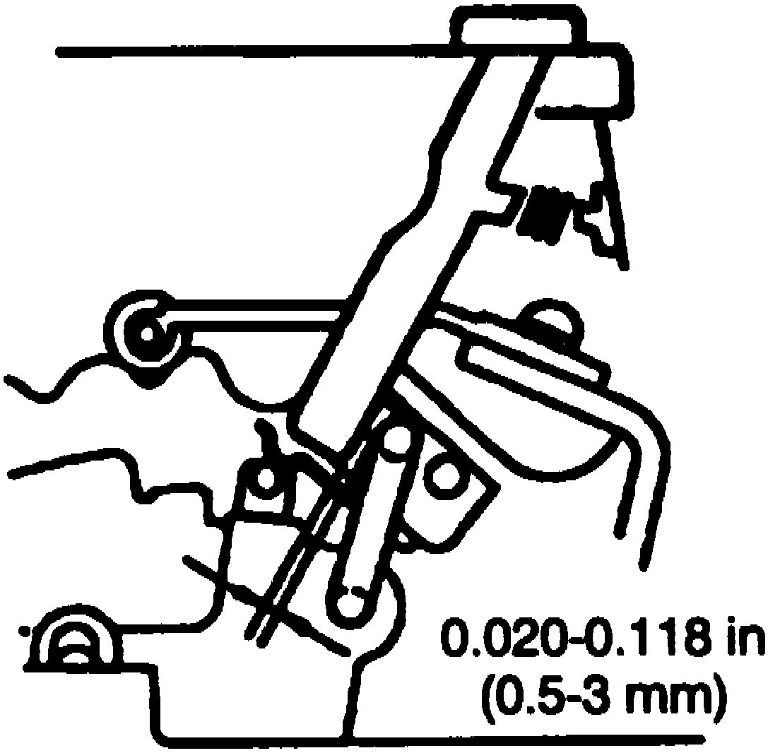
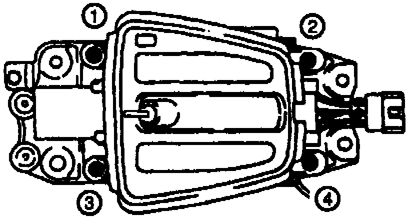
Fig. 22 Shift Indicator Plate Screw Tightening Sequence:
3. Reverse procedure to install noting the following:
a. When installing detent roller assembly, apply thin film of grease to inside of detent roller and install to spring plate, Fig. 19.
b. Shift selector lever to P range.
c. Loosely install spring plate, upper spring plate, and assist plate.
d. Adjust clearance between guide plate and guide pin, Fig. 20, then torque to 18-26 inch lbs.
e. When installing indicator, shift selector lever to P range.
f. Align screws in slider with holes in indicator panel, then secure with heavy gauge wire to hold slider.
g. Temporarily install indicator to selector lever bracket.
h. Ensure clearance between guide plate and guide pin are as outlined in, Fig. 21.
i. Tighten indicator screws in order as outlined in, Fig. 22, then remove wire.
j. Ensure selector lever properly aligns with indicator in each range.