Crankshaft

DISASSEMBLY
1. Remove the timing belt, cylinder head assembly, drive plate, transaxle mounting plate oil pan. For details, refer to their respective chapters.
2. Remove the oil seal case and the rear oil seal.
3. Remove the connecting rod caps.
NOTE: Mark the main bearing caps to reassemble in the original position and direction.
4. Remove the main bearing caps and remove the crank shaft. Keep the bearings in order by cap number.
INSPECTION CRANKSHAFT
1. Check the crankshaft journals and pins for damage, uneven wear and cracks. Also check the oil holes for restrictions. Repair or replace any defective part.
2. Inspect for out-of-roundness and taper of the crank shaft journal and pin.
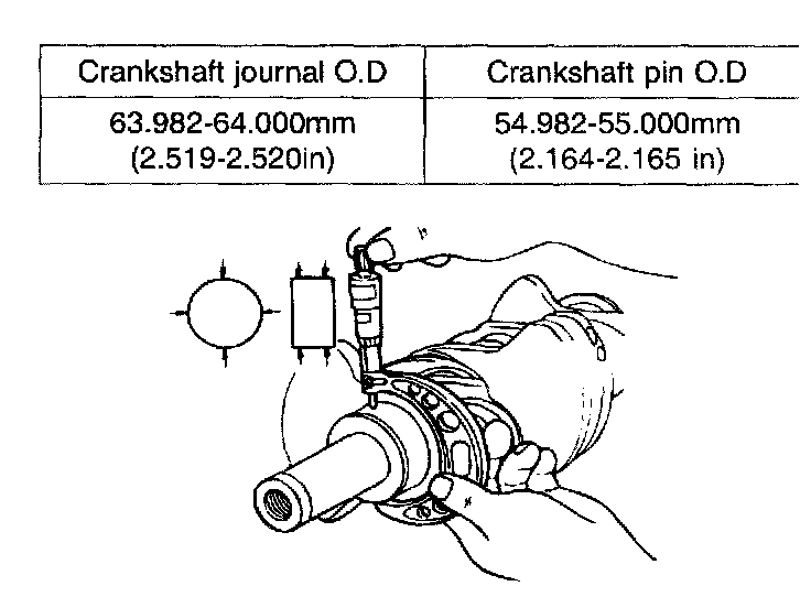
Standard value
MAIN BEARING AND CONNECTING ROD BEARING
Visually inspect each bearing for peeling, melt, seizure and improper contact. Replace any defective bearings.
OIL CLEARANCE MEASUREMENT
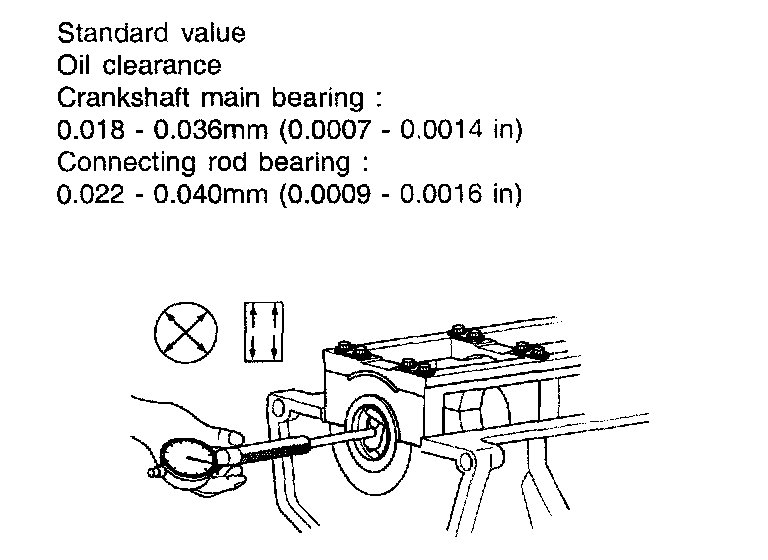
Check for oil clearance by measuring the Outside diameter of the crankshaft journal and the inside diameter of the bearing. The clearance can be obtained by calculating the difference between the measured outside and inside diameter.
PLASTIGAUGE METHOD
Plastigauge may be used to measure the clearance.
1. Remove oil and grease and any other dirt from the bearings and journals.
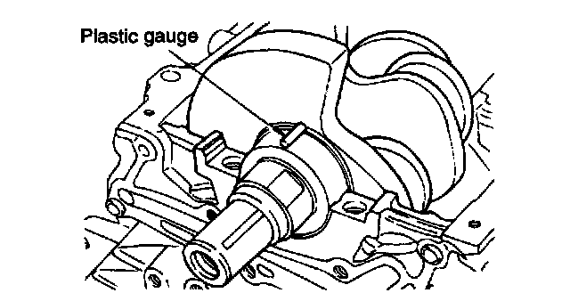
2. Cut the plastigauge to the same length as the width of the bearing and place it in parallel with the journal, avoiding the oil holes.
3. Install the crankshaft, bearings and caps and tighten them to the specified torques. During this operation, do not turn the crankshaft. Remove the caps. Measure the width of the widest part by using the scale printed on the gauge package.
If the clearance exceeds the repair limit, the bearing should be replaced or an undersize bearing should be used.
When installing a new crankshaft, be sure to use standard size bearings.
Should the standard clearance not be obtained even after bearing replacement, the journal and pin should be ground to undersize and a bearing of the corresponding undersize should be installed.
OIL SEAL
Check the front and rear oil seals for damage or worn surfaces.
Replace any seat that is defective.
DRIVING PLATE
Replace the distorted, damaged, or cracked drive plates.
REASSEMBLY
MAIN BEARING
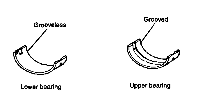
1. Install the grooved main bearing (upper bearing) on the cylinder block side.
2. Install the grooveless main bearing (lower bearing) on the main bearing cap side.
3. Install the crankshaft. Apply engine oil to the journal and pin.
4. Caps should be installed with the arrow mark directed toward the front of the engine. The cap number sequence must be correct.
5. Tighten all cap bolts to the specified torque shown in the picture.
Tightening torque
Main bearing cap bolt : 68.6 - 78.5 Nm (700 - 800 kgf-cm, 50.6 - 57.9 ft. lbs.)
6. Cap bolt should be tightened to specified torque in 4-5 steps before being tightened to the specified torque.
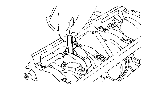
7. Make certain that the crankshaft turns freely and has the proper crankshaft end play.
Crankshaft end play
Standard value : 0.050 - 0.250 mm (0.00197 - 0.0098 inch)
Limit : 0.35 mm (0.014 inch)
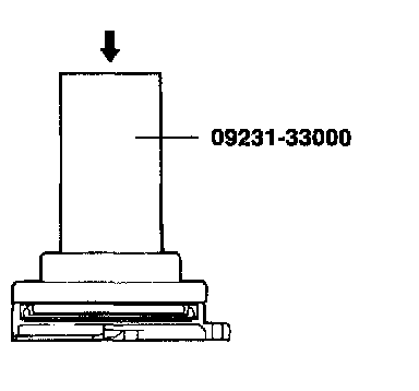
8. Assemble the rear oil seal to oil case using the special tool (09231-33000).
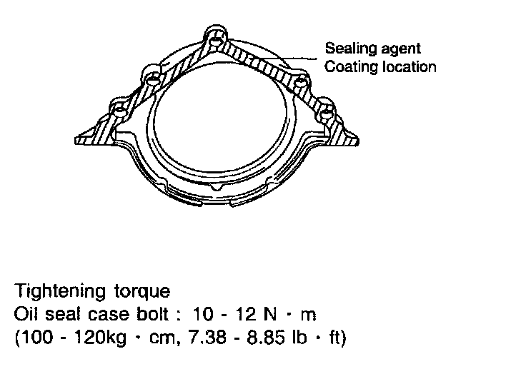
9. Smear sealant on area indicated in the figure and in stall the oil seal case in the cylinder block.
10. Install the rear plate to the specified torque.
Tightening torque
Rear plate : 10 - 12 Nm (100 - 120 kgf-cm, 7.38 - 8.85 ft. lbs.)
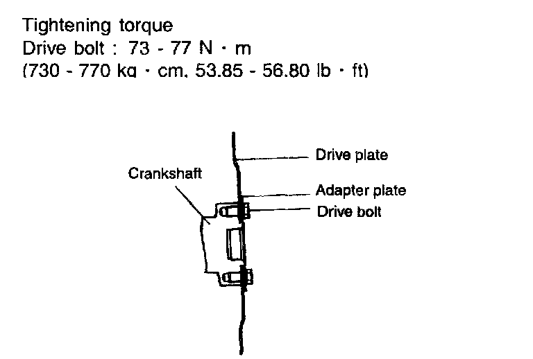
11. Install the drive plate and the adapter plate.
REPLACEMENT
CRANKSHAFT MAIN BEARING (3.5)
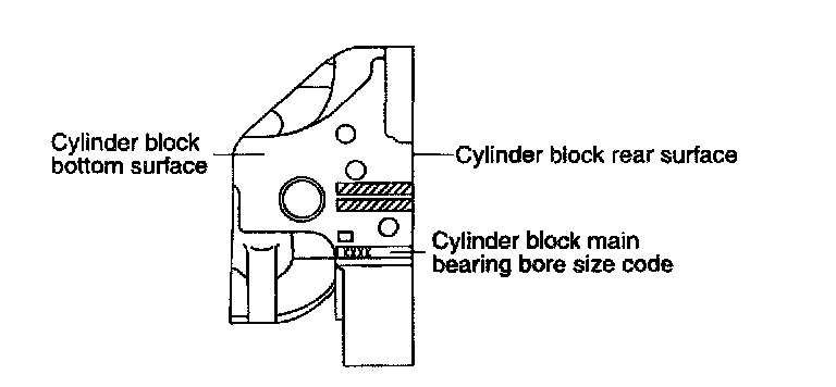
1. Check the cylinder block main bearing bore size code.
NOTE: Record the cylinder block main bearing bore size code letters on cylinder block. Reading order is from left to right with, front main bearing bore size code shown first.
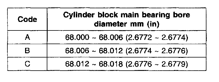
CYLINDER BLOCK MAIN BEARING BORE DIAMETER
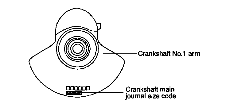
2. Check the crankshaft main journal size code.
NOTE: Record the main journal size code letters on the crankshaft balance weight. Reading order is from left to right, with No. 1 main journal size code shown first.
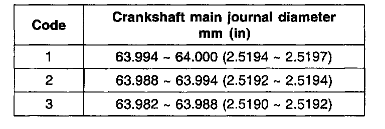
CRANKSHAFT MAIN JOURNAL DIAMETER
3. Choose proper main journal bearing.
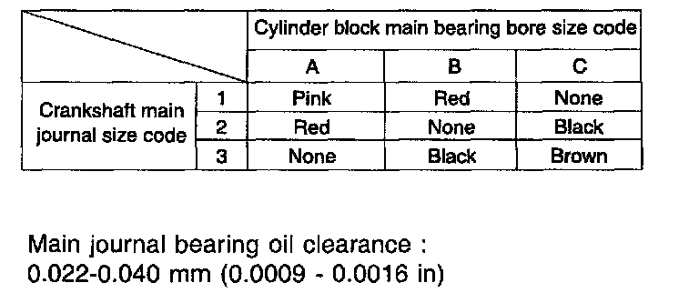
MAIN JOURNAL BEARING SELECTION TABLE

MAIN JOURNAL BEARING THICKNESS (REFERENCE DATA)