Accelerator Position Sensor (APS)
INSPECTION
FUNCTION AND OPERATION PRINCIPLE
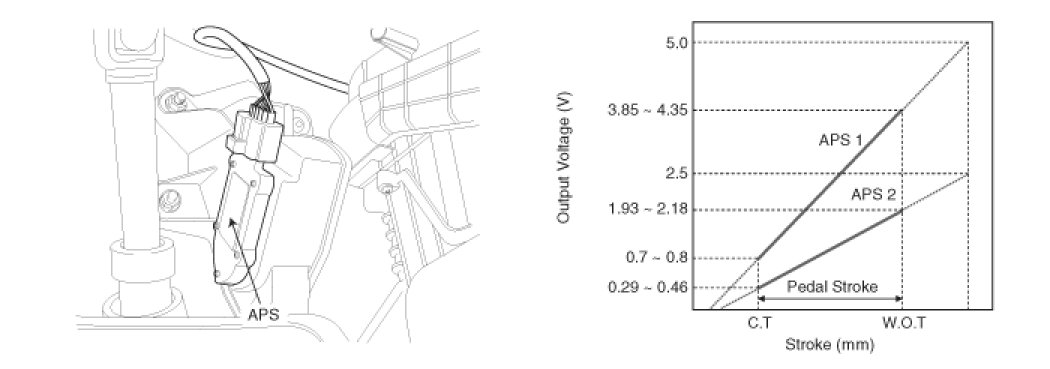
Accelerator Position Sensor (APS) is installed on the accelerator pedal module and detects the rotation angle of the accelerator pedal. The APS is one of the most important sensors in engine control system, so it consists of the two sensors which adapt individual sensor power and ground line. The second sensor monitors the first sensor and its output voltage is half of the first one. If the ratio of the sensor 1 and 2 is out of the range (approximately 1/2), the diagnostic system judges that it is abnormal.
SPECIFICATION


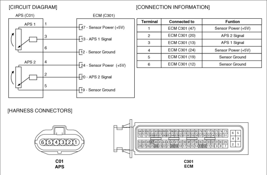
SCHEMATIC DIAGRAM
COMPONENT INSPECTION
1. Connect a scan tool to the Diagnosis Link Connector (DLC).
2. Start engine and check output voltages of APS 1 and 2 at C.T and W.O.T.
Specification: Refer to SPECIFICATION.
3. Turn ignition switch OFF and disconnect the scantool from the DLC.
4. Disconnect APS connector and measure resistance between APS terminals 1 and 6 (APS 1).
Specification: Refer to SPECIFICATION.
5. Disconnect APS connector and measure resistance between APS terminals 4 and 5 (APS 2).
Specification: Refer to SPECIFICATION.