How to Use the Circuit Diagrams
How To Use The Circuit Diagrams
Power Distribution
The Power Distribution diagram shows the connections from the battery to the engine, passenger, and where applicable, rear fuse box. It also shows the internal circuitry of the fuse boxes.
The fuse box details are followed by independent functionally specific circuits and then a splices and centre taps section outlining the way in which internal harness splices and centre taps distribute power in the harnesses. This information should be used during diagnosis of electrical faults to check for symptoms in associated circuits and narrow down the search area.
Earth Distribution
The earth distribution section comprises a number of Headers and Splices circuits. These are used in a similar manner to those in Power Distribution; to narrow the search area by checking for fault symptoms in associated circuits.
Splices and centre taps
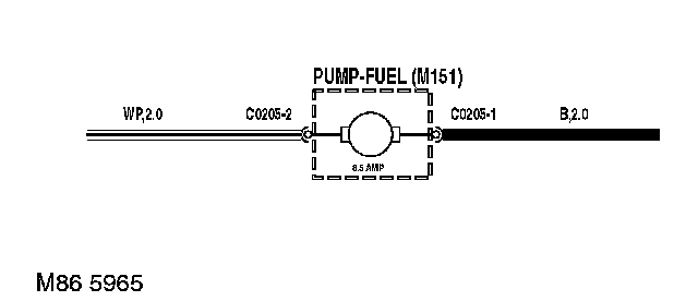
Header and splice tables present the joint(s) and wiring up to the first component. Splices are identified by a number with an alphabetical prefix and the wire colour.
The splice information shown on individual system circuits is not complete. Always refer to the splices circuit for complete information on each splice.
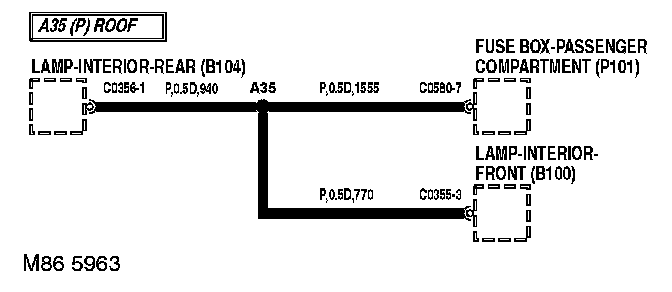
Wire length (Power & Earth Distribution only)
The length of the wire is shown in millimetres. This can be used to locate internal harness splices; look for the shortest wire between the joint and connector. For example, it can be seen that C0580-7 is 1555 mm from joint A35.
Connectors
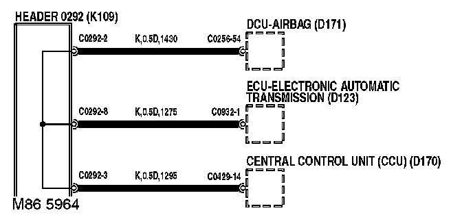
Header joints are identified by their corresponding connector number with a numbered suffix to indicate the pin-out detail of the wire, i.e. C0292-1 identifies connector 292, pin number 1. Wire insulation colour is identified in the normal way. Where wires have a predominant colour with a secondary colour tracer, the main colour is identified first, i.e. LGS - Light Green with a Slate tracer.
Line Types
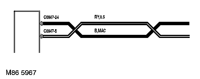
This denotes the wires are a twisted pair.
These sheet break symbols indicate the circuit continues on later sheets.
The cup and ball symbol indicates the male and female halves of connector.
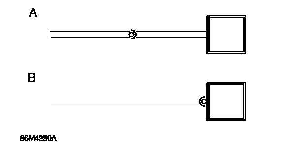
A. Plug on lead (Flylead) wired directly to the component.
B. Connector plugs directly into component.
Components
The name or description of the component is shown. A dotted outline indicates that the component is not shown in its entirety.
Earth points
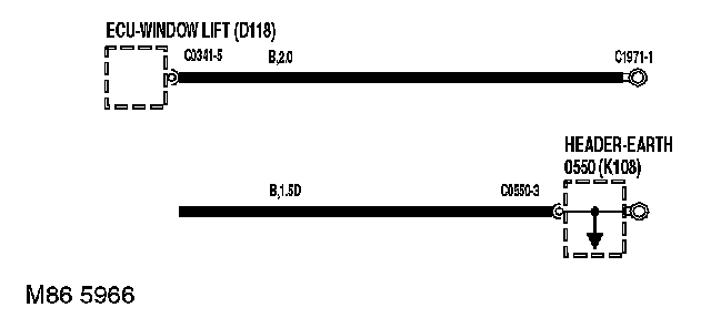
Earth points are identified with an eyelet symbol and a connector number, except where components are grounded through their fixings, when only the eyelet is shown.
Fuses and Diodes
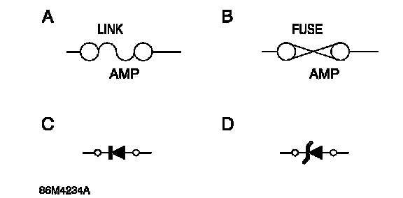
Fusible links (A) and current rated fuses (B) are identified as shown.
The direction of the arrow in a Diode symbol (C) indicates the direction of current flow. The Zener diode (D) - prevents current flow until a precise voltage is reached.