Steering Column: Service and Repair
Column Assembly - Inner & Outer
Service Repair No - 57.40.01
Before disconnecting the battery, ensure all text and cautions are observed.
Remove
1. Move drivers seat fully rearwards for access.
2. Remove drivers side footwell closing panel.
3. Secure bonnet in upright position using service clips.
4. If steering wheel is not locked, turn wheel to obtain better access to steering column shaft upper Torx clamp bolt.
5. Disconnect battery earth lead.
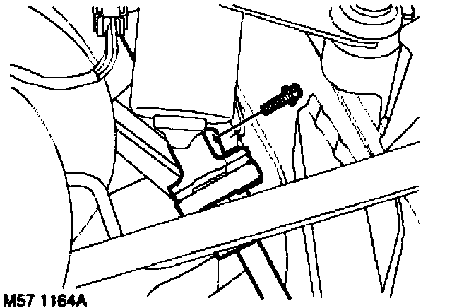
6. Working from under bonnet, remove and discard upper Torx bolt from steering coupling.
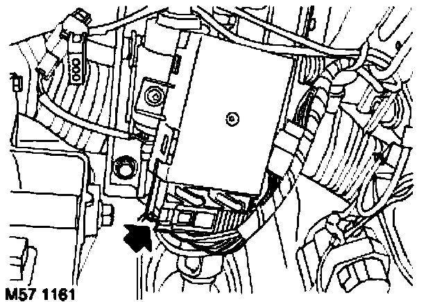
7. Remove rotary coupler assembly.
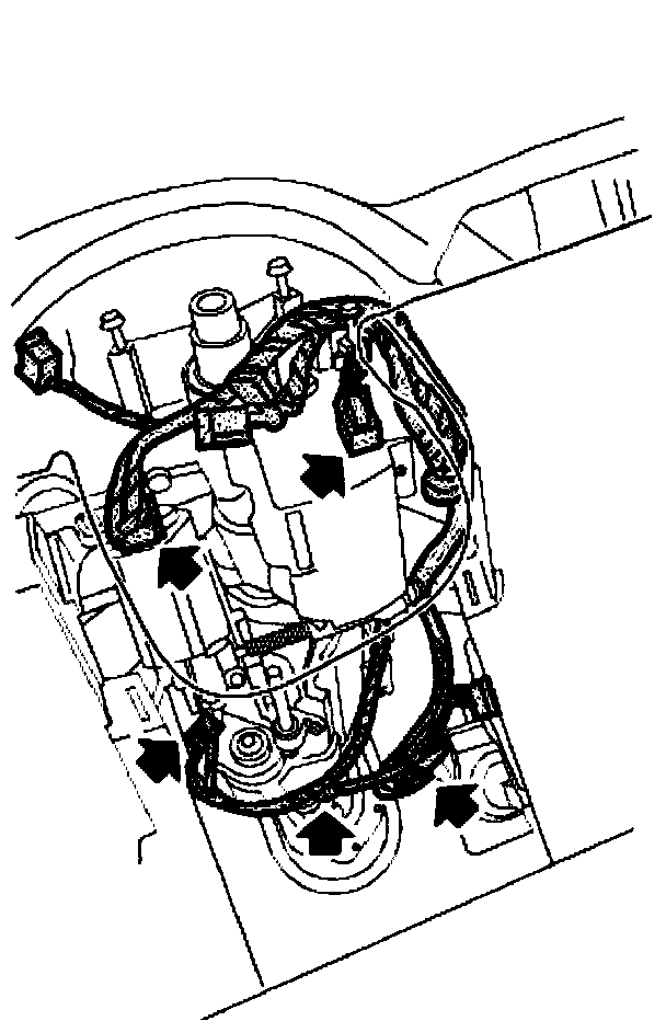
8. Models with manual steering column control only: Disconnect multiplug from steering column control module.
9. Disconnect multiplugs from steering column adjustment and lock motors.
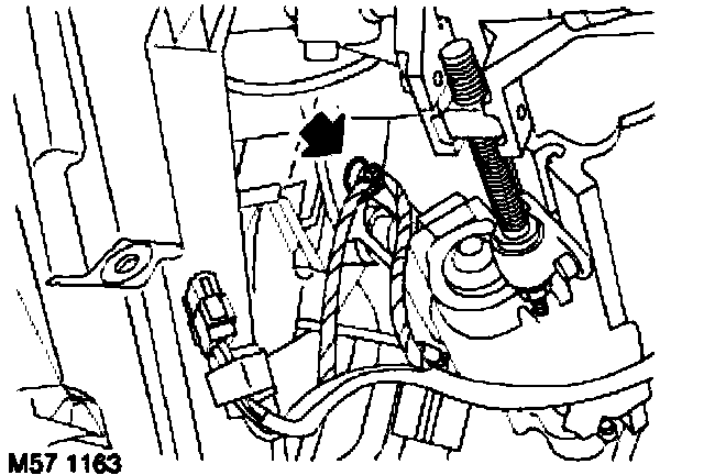
10. Remove cable tie and disconnect multiplug from steering angle sensor.
Protect fascia shroud adjacent to steering column aperture.
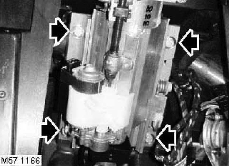
11. Release closing panel light harness, from securing clip in column frame.
12. Remove 4 bolts from steering column, carefully release column shaft from steering coupling and with assistance, remove column assembly from vehicle.
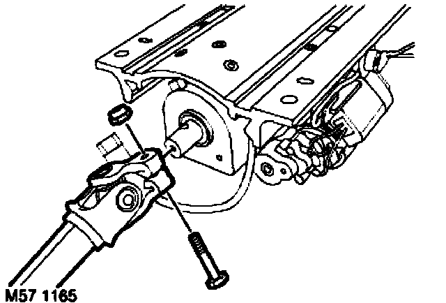
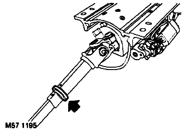
13. Ensure nylon sealing ring is fitted to steering shaft. If sealing ring is missing, remove it from column gaiter and fit to redundant steering shaft.
NOTE: Do not carry out further dismantling if component is removed for access only.
14. Remove nut and bolt from lower steering shaft to column, remove shaft.
15. Models with manual steering column control only: Remove 2 screws from steering control module and remove module
Refit
1. Models with manual steering column control only: Fit steering control module, secure with screws.
2. Fit lower steering shaft to column and secure with nut and bolt, tighten to 25 Nm (18 ft. lbs.).
3. Lubricate steering column nylon sealing ring.
4. Carefully position steering column assembly to vehicle. With assistance align steering column shaft to steering coupling, ensure groove in shaft aligns with bolt hole in steering column.
5. Fit steering coupling Torx bolt to ensure shaft is correctly aligned.
6. Ensure nylon sealing ring is located in groove within steering column gaiter.
7. Fit and finger tighten bolts securing steering column to fascia rail.
8. Ensure fascia rail locating pegs are aligned to steering column assembly, tighten bolts to 25 Nm (18 ft. lbs.).
9. Working from under bonnet, tighten steering coupling Torx bolt to 25 Nm (18 ft. lbs.).
10. Fit closure panel light harness clip to frame and secure harness to column.
11. Connect multiplug to steering angle sensor, secure harness with cable tie.
12. Connect multiplugs to steering column adjustment and lock motors.
13. Models with manual steering column control only: Connect multiplug to steering column control module.
14. Fit rotary coupler assembly.
15. Fit drivers side footwell closing panel.
16. Connect battery earth lead.
17. Connect bonnet support gas struts to body.
18. Check operation of steering column tilt, extension and lock motors.
19. Testbook/T4 must be used to initiate a new steering angle sensor. The initiation procedure can be found in Testbook/T4 by selecting the following icons.
^ System diagnosis
^ ABS
^ Vehicle maintenance