Air Injection Pump: Service and Repair
Air Pump:

Air Pump:

Air Pump:

Air Pump:

REMOVAL
1. DISCHARGE FUEL SYSTEM PRESSURE
2. DISCONNECT CABLE FROM NEGATIVE BATTERY TERMINAL
CAUTION: Wait at least 90 seconds after disconnecting the cable from the negative (-) battery terminal to prevent airbag and seat belt pretensioner activation.
3. DRAIN ENGINE COOLANT
4. REMOVE V-BANK COVER SUB-ASSEMBLY
5. DISCONNECT FUEL RETURN HOSE
6. DISCONNECT FUEL MAIN HOSE
7. REMOVE INTAKE AIR CONNECTOR PIPE
8. REMOVE INTAKE MANIFOLD ASSEMBLY
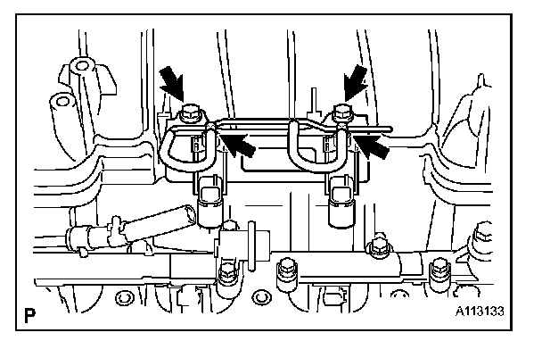
9. REMOVE VACUUM CONTROL VALVE SET (for Air Injection System)
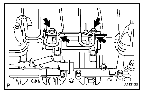
a. Remove the 2 bolts and valve set from the intake manifold.
b. Remove the 2 vacuum hoses from the valve set.
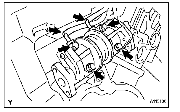
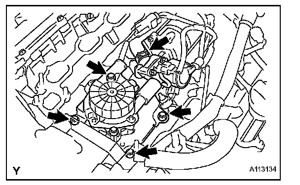
10. REMOVE AIR PUMP ASSEMBLY

a. Disconnect the No. 2 air hose from the air switching valve.
b. Disconnect the air switching valve connector.
c. Disconnect the pressure sensor connector for the air injection system.
d. Remove the 4 bolts and air pump.
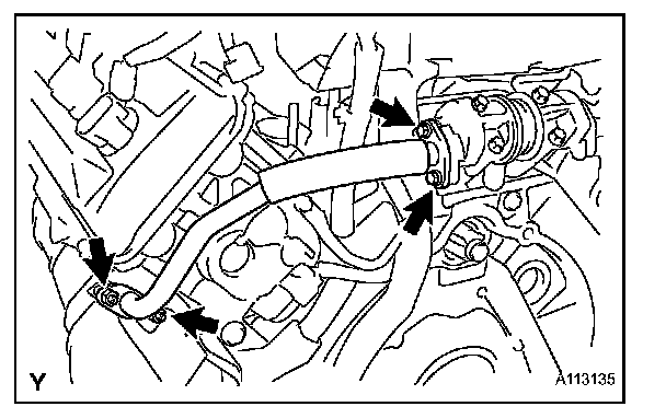
11. REMOVE NO. 2 AIR SWITCHING VALVE
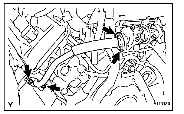
a. Remove the 4 nuts and 2 gaskets, and disconnect the 2 No. 3 air tubes from the exhaust manifolds.
b. Remove the 4 bolts, 2 gaskets and the 2 No. 3 air tubes from the 2 No. 2 air switching valves.

c. Remove the 4 bolts, 2 gaskets and the 2 No. 2 air switching valves from the rear water by-pass joint.
d. Remove the 2 vacuum hoses from the No. 2 air switching valves.
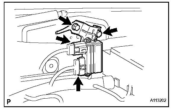
12. REMOVE AIR INJECTION CONTROL DRIVER
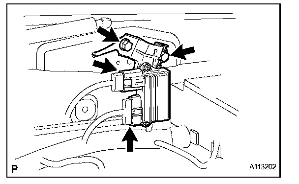
a. Disconnect the 2 connectors from the air injection control driver.
b. Remove the 2 bolts and air injection control driver from the vehicle body.
DISASSEMBLY
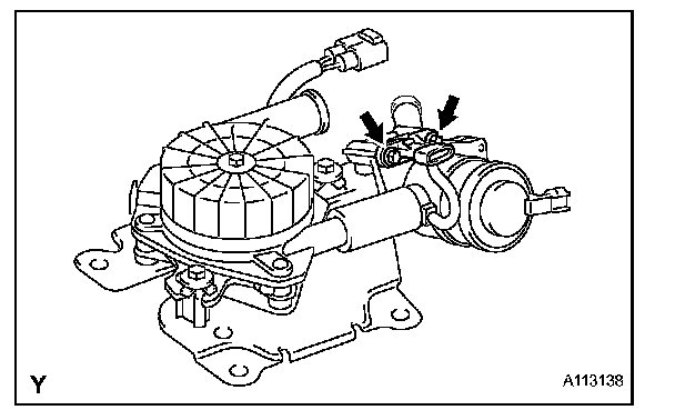
1. REMOVE PRESSURE SENSOR
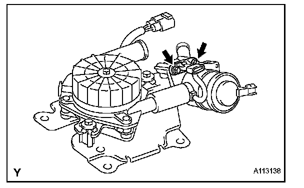
a. Remove the vacuum hose from the pressure sensor and air switching valve.
b. Remove the 2 bolts and pressure sensor from the air switching valve.
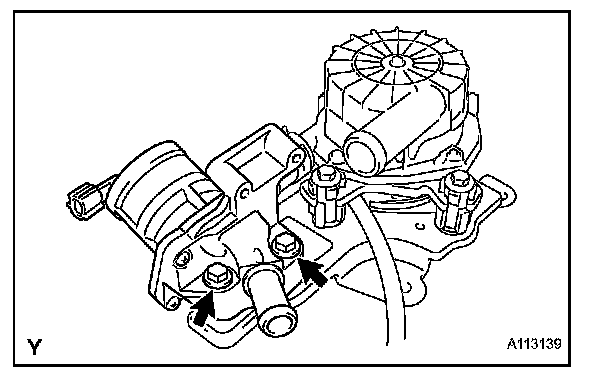
2. REMOVE AIR SWITCHING VALVE
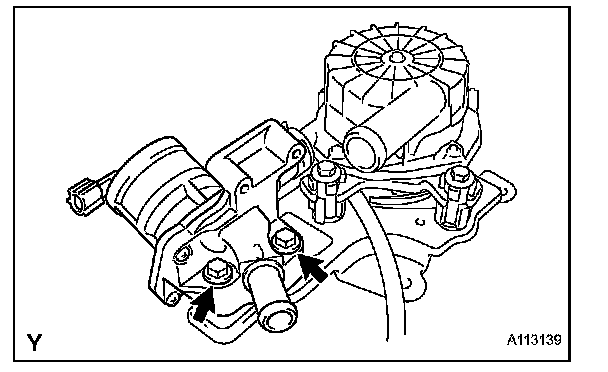
a. Remove the 2 bolts and air switching valve from the air pump bracket.
b. Remove the No. 1 air hose from the air switching valve and air pump.
REASSEMBLY
1. INSTALL AIR SWITCHING VALVE
a. Install the No. 1 air hose to the air switching valve and air pump.
b. Install the air switching valve to the air pump bracket with the 2 bolts.
Torque: 16 N.m (163 kgf.cm, 12 ft.lbf)
2. INSTALL PRESSURE SENSOR
a. Install the pressure sensor to the air switching valve with the 2 bolts.
Torque: 5.0 N.m (55 kgf.cm, 48 in.lbf)
b. Install the vacuum hose to the pressure sensor and air switching valve.
INSTALLATION
1. INSTALL AIR INJECTION CONTROL DRIVER
a. Install the air injection control driver to the body with the 2 bolts.
Torque: 19.5 N.m (198 kgf.cm, 14 ft.lbf)
b. Connect the 2 connectors to the air injection control driver.
2. INSTALL NO.2 AIR SWITCHING VALVE
a. Connect the 2 vacuum hoses to the 2 No. 2 air switching valves.
b. Install 2 new gaskets and 2 No. 2 air switching valves to the rear water by-pass joint with the 4 bolts.
Torque: 10 N.m (102 kgf.cm, 7 ft.lbf)
c. Install 2 new gaskets, and connect the 2 No. 3 air tubes to the No. 2 air switching valve with the 4 bolts.
Torque: 10 N.m (102 kgf.cm, 7 ft.lbf)
d. Install the 2 new gaskets, and connect the 2 No. 3 air tubes to the exhaust manifold with the 4 nuts.
Torque: 10 N.m (102 kgf.cm, 7 ft.lbf)
3. INSTALL AIR PUMP ASSEMBLY
a. Install the air pump with the 4 bolts.
Torque: 16 N.m (163 kgf.cm, 12 ft.lbf)
b. Connect the pressure sensor connector for the air injection systems.
c. Connect the air switching valve connector.
d. Connect the No. 2 air hose to the air switching valve.
4. INSTALL VACUUM CONTROL VALVE SET (for Air Injection System)
a. Install the valve set to the intake manifold with the 2 bolts.
Torque: 7.5 N.m (76 kgf.cm, 66 in.lbf)
b. Connect the 2 vacuum hoses to the valve set.
5. INSTALL INTAKE MANIFOLD ASSEMBLY
6. CONNECT FUEL MAIN HOSE
7. CONNECT FUEL RETURN HOSE
8. INSTALL INTAKE AIR CONNECTOR PIPE
9. INSTALL V-BANK COVER SUB-ASSEMBLY
10. CONNECT CABLE TO NEGATIVE BATTERY TERMINAL
11. PERFORM INITIALIZATION
a. Perform initialization.
NOTE: Certain systems need to be initialized after disconnecting and reconnecting the cable from the negative (-) battery terminal.
12. ADD ENGINE COOLANT
13. CHECK FOR ENGINE COOLANT LEAKS
Check for the engine coolant leaks.
14. CHECK FOR FUEL LEAKS