Emergency Contact Module: Service and Repair
REMOVAL1. REMOVE REAR SEAT ASSEMBLY RH
2. REMOVE REAR SEAT ASSEMBLY LH
3. REMOVE QUARTER SCUFF PLATE INSIDE LH
4. REMOVE QUARTER SCUFF PLATE INNER RH
5. REMOVE NO. 3 SEAT ANCHOR RAIL
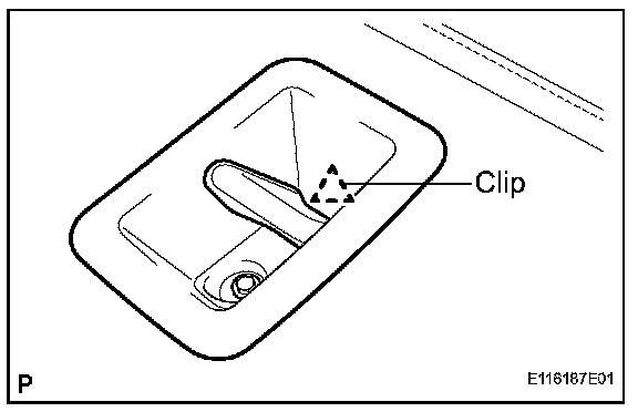
a. Remove the screw.
b. Disengage the clip and remove the No. 3 seat anchor rail.
6. REMOVE NO. 1 SEAT ANCHOR RAIL
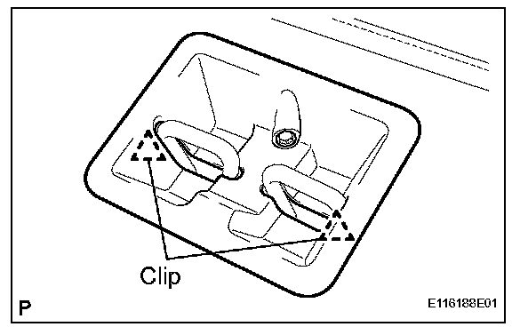
a. Remove the screw.
b. Disengage the 2 clips and remove the No. 1 seat anchor rail.
7. REMOVE NO. 2 SEAT ANCHOR RAIL RH
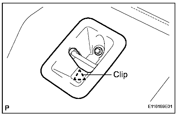
a. Remove the screw.
b. Disengage the clip and remove the No. 2 seat anchor rail RH.
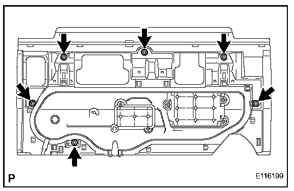
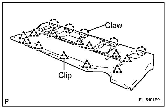
8. REMOVE MOBILE PHONE COVER
a. Turn back the floor carpet.
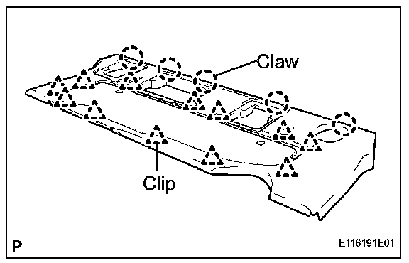
b. Disengage the 12 clips.
c. Disengage the 5 claws and remove the mobile phone cover.
9. REMOVE MAYDAY ECU ASSEMBLY
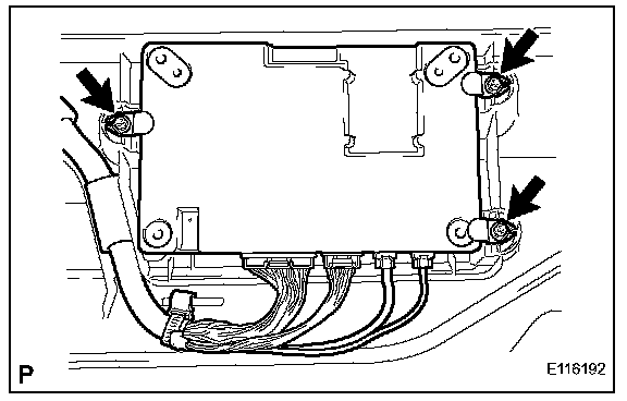
a. Remove the 3 screws and the 3 mobile phone brackets.
b. Disconnect the 4 connectors and remove the Mayday ECU.
10. REMOVE MAYDAY BATTERY
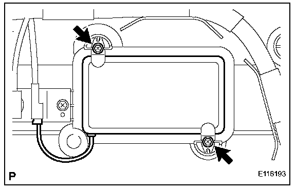
a. Remove the 2 screws and the 2 mobile phone brackets.
b. Disconnect the connector and remove the Mayday battery.
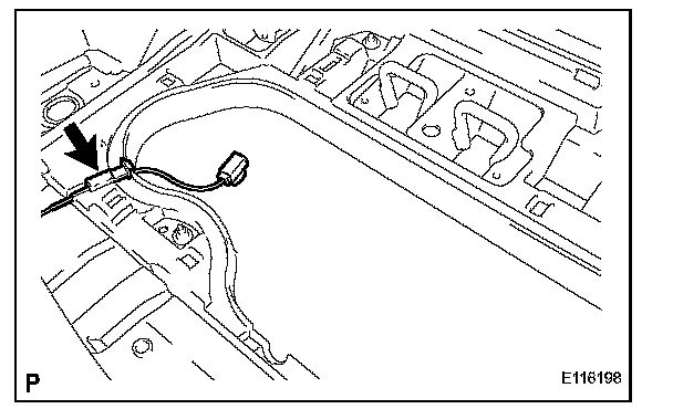
11. REMOVE MAYDAY WIRE
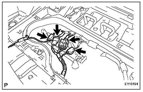
a. Disconnect the 4 connectors.
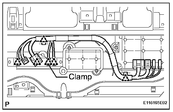
b. Disengage the 6 clamps and remove the Mayday wire.
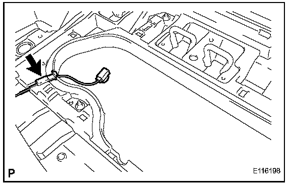
12. REMOVE MOBILE PHONE BRACKET
a. Disengage the wire harness clamp from the mobile phone bracket.
b. Remove the 2 screws and the mobile phone bracket.
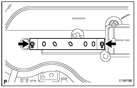
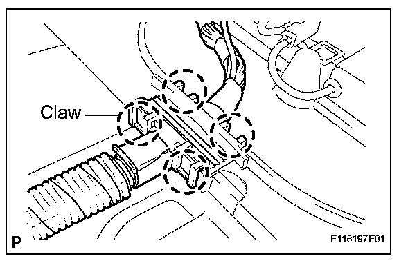
13. REMOVE TELEPHONE BRACKET
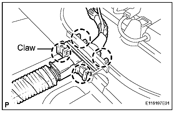
a. Disengage the 4 claws of the wire harness clamp and disconnect the wire harness.
b. Disengage the wire harness clamp.
c. Remove the 6 nuts and the telephone bracket.
INSTALLATION
NOTE: When replacing the Mayday ECU, wire down the ESN and STID numbers that are located on the new Mayday ECU label. Then numbers may be required to register and enroll the ECU with the LEXUS Link Call Center.
1. INSTALL TELEPHONE BRACKET
a. Install the telephone bracket with the 6 nuts.
b. Securely engage the wire harness clamp.
c. Securely engage the 4 claws of the wire harness clamp.
2. INSTALL MOBILE PHONE BRACKET
3. INSTALL MAYDAY WIRE
4. INSTALL MAYDAY BATTERY
5. INSTALL MAYDAY ECU ASSEMBLY
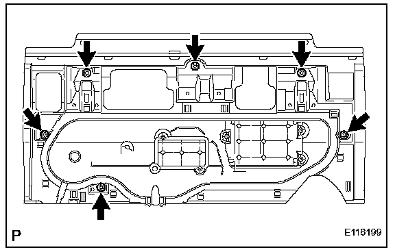
6. INSTALL MOBILE PHONE COVER
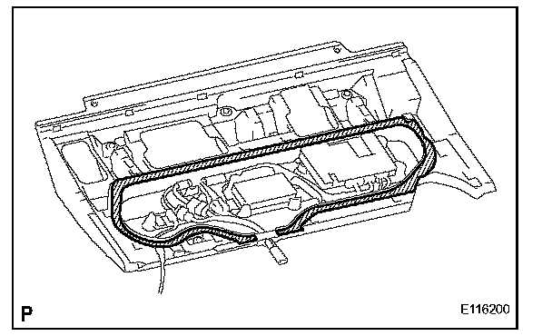
a. Make sure that there is no foreign matter in the shaded area as shown in the illustration.
b. Fit the 5 claws into the holes of the telephone bracket.
c. Push in the 12 clips of the mobile phone cover to securely engage the cover.
7. INSTALL NO. 2 SEAT ANCHOR RAIL RH
8. INSTALL NO. 1 SEAT ANCHOR RAIL
9. INSTALL NO. 3 SEAT ANCHOR RAIL
10. INSTALL QUARTER SCUFF PLATE INNER RH
11. INSTALL QUARTER SCUFF PLATE INSIDE LH
12. INSTALL REAR SEAT ASSEMBLY RH
13. INSTALL REAR SEAT ASSEMBLY LH