Part 2
DISASSEMBLY(continued)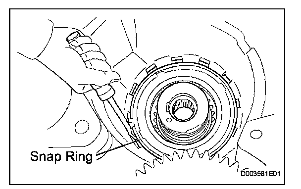
41. REMOVE UNDERDRIVE ONE-WAY CLUTCH ASSEMBLY
(a) Using a screwdriver, remove the snap ring from the transaxle case.
NOTICE: Do not apply excessive force when removing the snap ring.
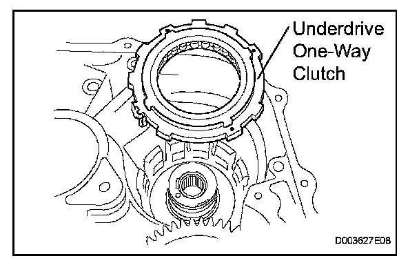
(b) Remove the underdrive one-way clutch from the transaxle case.
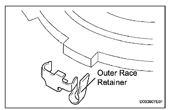
(c) Remove the outer race retainer from the one-way clutch.
42. REMOVE NO. 2 UNDERDRIVE CLUTCH DISC
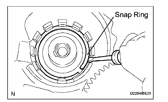
(a) Using a screwdriver, remove the snap ring.
NOTICE: Do not apply excessive force when removing the snap ring.
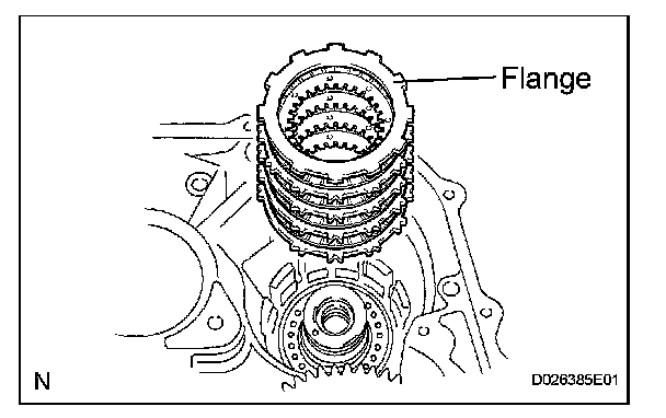
(b) Remove the flange, 4 discs, and 4 plates from the transaxle case.
43. INSPECT NO. 2 UNDERDRIVE CLUTCH DISC
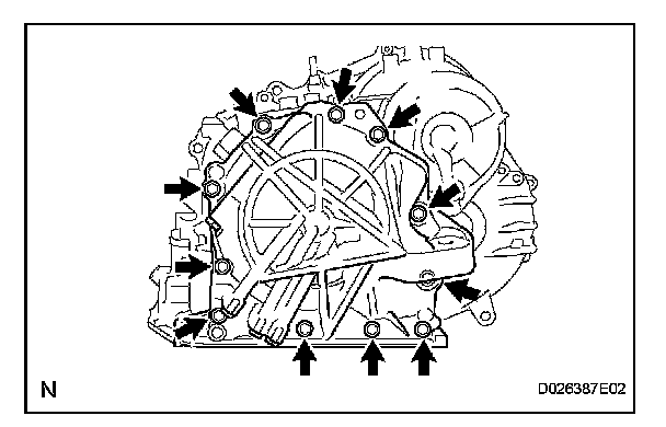
44. REMOVE TRANSAXLE REAR COVER SUB-ASSEMBLY
(a) Remove the 11 bolts.
(b) Tap on the circumference of the rear cover with a plastic hammer to remove the transaxle rear cover from the transaxle case.
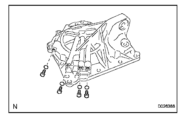
45. REMOVE NO. 1 TRANSAXLE CASE PLUG
(a) Remove the 4 No. 1 transaxle case plugs from the transaxle rear cover.
(b) Remove the 4 No. 1 O-rings from the 4 transaxle case plugs.
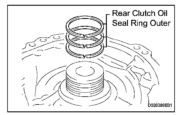
46. REMOVE REAR CLUTCH OIL SEAL RING OUTER
(a) Remove the 3 rear clutch oil seal rings from the transaxle rear cover.
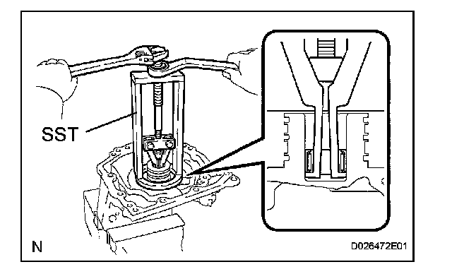
47. REMOVE NEEDLE ROLLER BEARING
(a) Using SST, remove the needle roller bearing from the transaxle rear cover.
SST 09387-00041 (09387-01021, 09387-01030, 09387-01040)
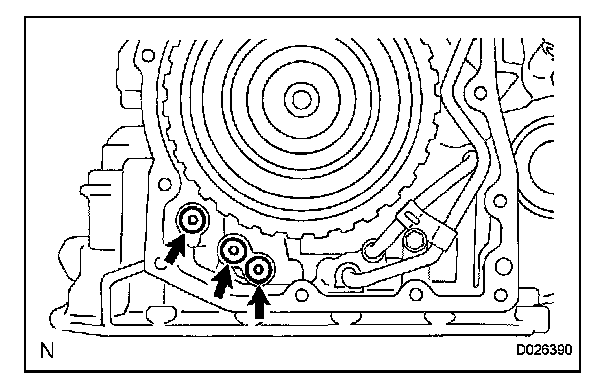
48. REMOVE NO. 1 GOVERNOR APPLY GASKET
(a) Using a screwdriver, remove the 3 apply gaskets.
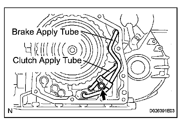
49. REMOVE BRAKE APPLY TUBE
(a) Remove the bolt, clamp, and brake apply tube.
(b) Remove the clutch apply tube.
(c) Remove the brake apply tube from the clamp.
NOTICE: Do not bend the tubes.
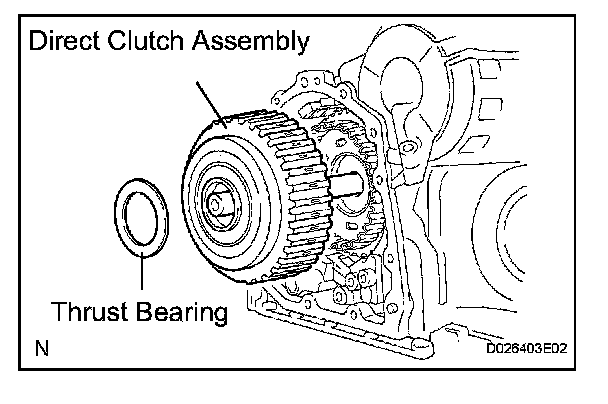
50. REMOVE DIRECT CLUTCH ASSEMBLY
(a) Remove the thrust bearing and the direct clutch assembly from the transaxle case.
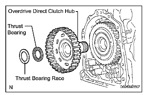
51. REMOVE OVERDRIVE DIRECT CLUTCH HUB SUB-ASSEMBLY
(a) Remove the thrust bearing race, thrust bearing, and overdrive direct clutch hub from the planetary gear assembly.
52. INSPECT OVERDRIVE DIRECT CLUTCH DRUM SUB-ASSEMBLY
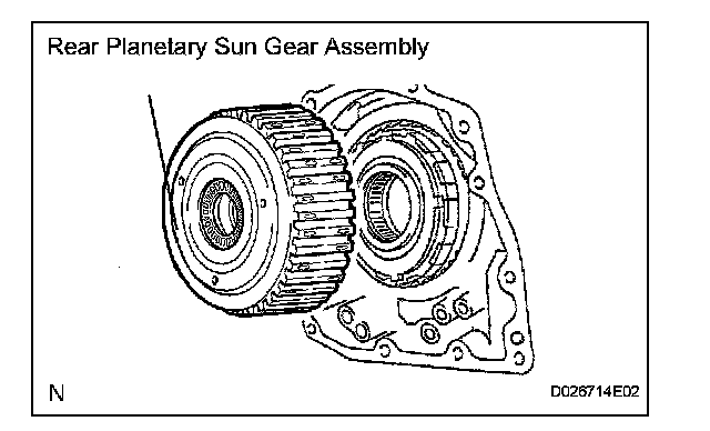
53. REMOVE REAR PLANETARY SUN GEAR ASSEMBLY
(a) Remove the rear planetary sun gear assembly from the transaxle case.
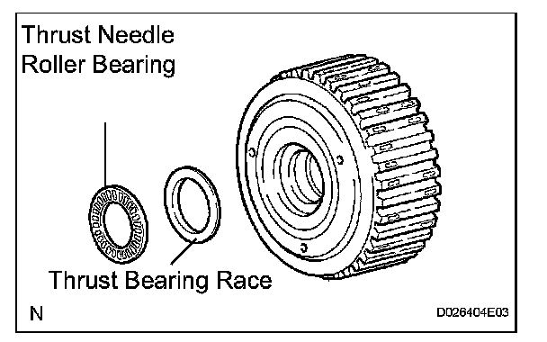
(b) Remove the thrust needle roller bearing and thrust bearing race from the rear planetary sun gear assembly.
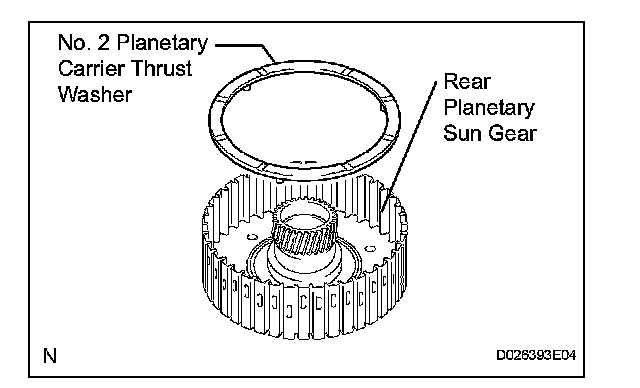
(c) Remove the No. 2 planetary carrier thrust washer from the rear planetary sun gear assembly.
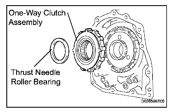
54. REMOVE ONE-WAY CLUTCH ASSEMBLY
(a) Remove the one-way clutch assembly and the thrust needle roller bearing from the transaxle case.
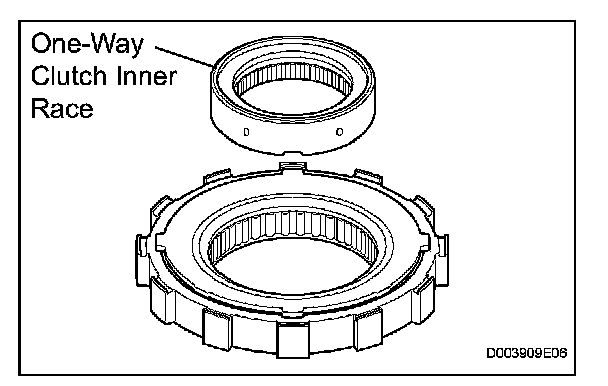
(b) Remove the one-way clutch inner race from the one-way clutch assembly.
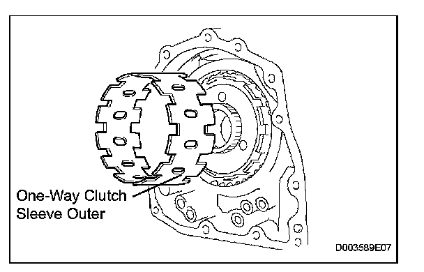
55. REMOVE ONE-WAY CLUTCH SLEEVE OUTER
(a) Remove the one-way clutch sleeve outer from the transaxle case.
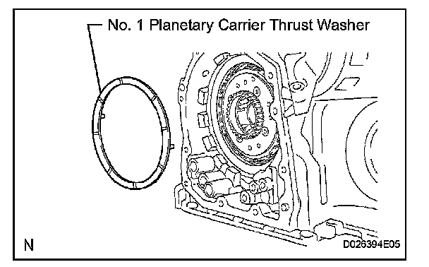
56. REMOVE NO. 1 PLANETARY CARRIER THRUST WASHER
(a) Remove the No. 1 planetary carrier thrust washer from the planetary gear assembly.
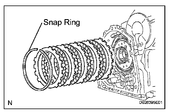
57. REMOVE 2ND BRAKE CLUTCH DISC
(a) Using a screwdriver, remove the snap ring.
(b) Remove the flange, 4 discs, and 4 plates from the transaxle case.
58. INSPECT 2ND BRAKE CLUTCH DISC
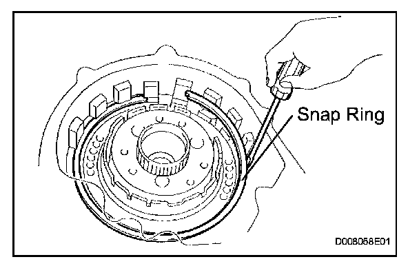
59. REMOVE 2ND BRAKE PISTON ASSEMBLY
(a) Using a screwdriver, remove the snap ring.
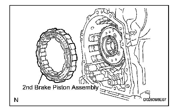
(b) Remove the 2nd brake piston assembly from the transaxle case.
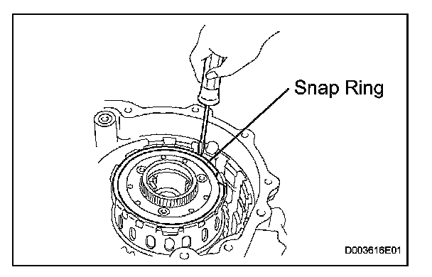
60. REMOVE REAR PLANETARY GEAR ASSEMBLY
(a) Using a screwdriver, remove the snap ring.
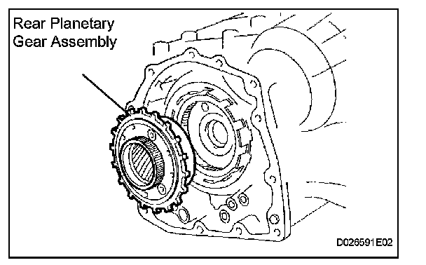
(b) Remove the rear planetary gear assembly from the transaxle case.
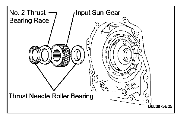
61. REMOVE INPUT SUN GEAR
(a) Remove the 2 thrust needle roller bearings, No. 2 thrust bearing race, and the input sun gear from the transaxle case.
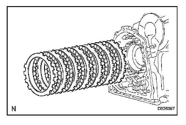
62. REMOVE 1ST AND REVERSE BRAKE CLUTCH DISC
(a) Remove the flange, 6 discs, and 6 plates from the transaxle case.
63. INSPECT 1ST AND REVERSE BRAKE CLUTCH DISC
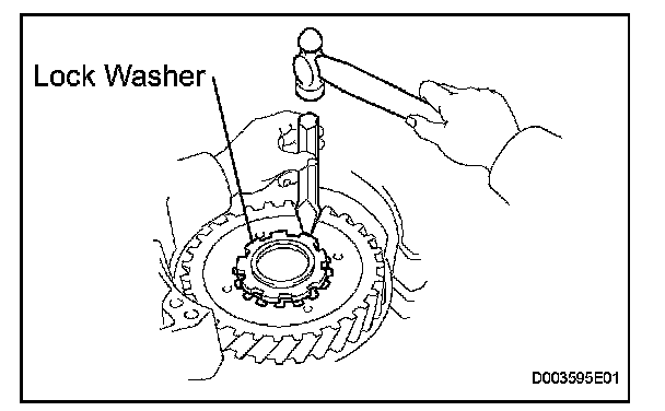
64. REMOVE FRONT PLANETARY GEAR ASSEMBLY
(a) Using a chisel and hammer, unstake the lock washer.
NOTICE: Push down all claws of the washer. Otherwise, the SST cannot be fully pressed against the nut, and the nut cannot be loosened.
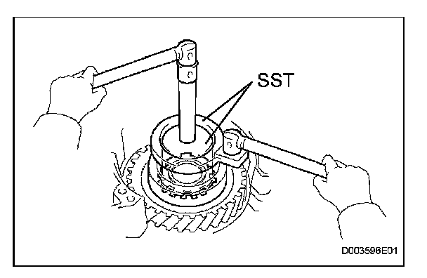
(b) Using SST, remove the nut.
SST 09387-00030, 09387-00080
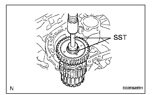
(c) Using SST and a press, remove the front planetary gear assembly from the counter drive gear.
SST 09950-60010 (09951-00450), 09950-70010 (09951-07100)
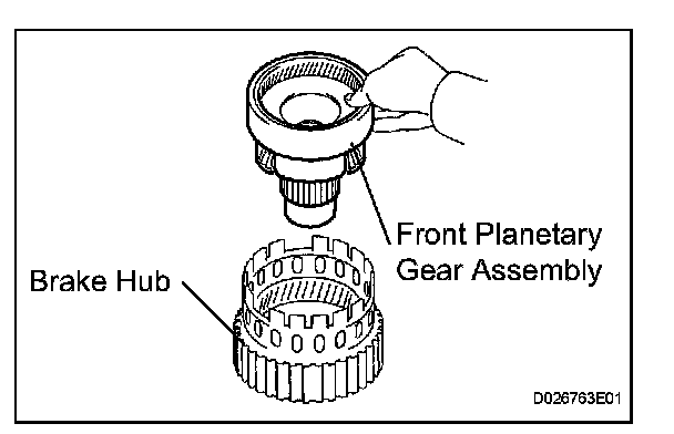
(d) Remove the front planetary gear assembly from the brake hub.
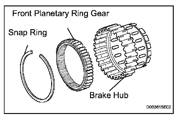
65. REMOVE FRONT PLANETARY RING GEAR
(a) Using a screwdriver, remove the snap ring and front planetary ring gear from the brake hub.
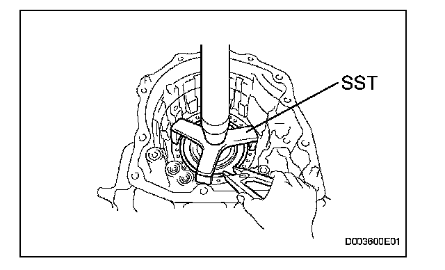
66. REMOVE 1ST AND REVERSE BRAKE RETURN SPRING SUB-ASSEMBLY
(a) Place SST on the return spring, and compress the return spring with a press.
SST 09387-00070
(b) Using a snap ring expander, remove the snap ring.
NOTICE:
^ Stop the press when the spring seat is lowered 1 to 2 mm (0.039 to 0.078 in.) from the snap ring groove to prevent the spring seat from being deformed.
^ Do not expand the snap ring excessively.
67. INSPECT 1ST AND REVERSE BRAKE RETURN SPRING SUB-ASSEMBLY
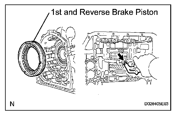
68. REMOVE 1ST AND REVERSE BRAKE PISTON
(a) Apply compressed air (392 kPa, 4.0 kgf/cm2, 57 psi) to the transaxle case to remove the 1st and reverse brake piston.
NOTICE:
^ Applying compressed air may cause the piston to jump-out. When removing the piston, hold it using a shop rag or a piece of cloth.
^ Take care not to splash ATF when applying compressed air.
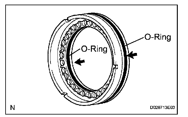
(b) Remove the 2 O-rings from the 1st and reverse brake piston.
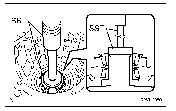
69. REMOVE COUNTER DRIVE GEAR
(a) Using SST and a press, remove the counter drive gear from the transaxle case.
SST 09950-60010 (09951-00590), 09950-70010 (09951-07100)
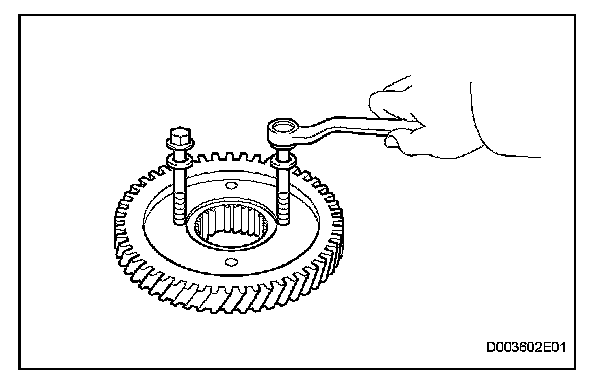
(b) As shown in the illustration, tighten the 2 bolts evenly and make clearance of approximately 20.0 mm (0.787 in.) between the counter drive gear and the inner race.
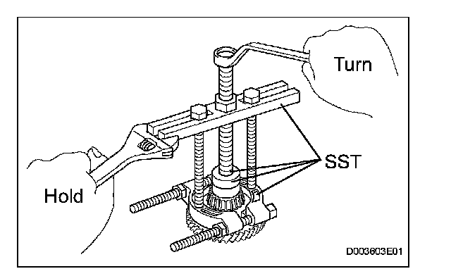
(c) Using SST, remove the tapered roller bearing.
SST 09950-60010 (09951-00590), 09950-00020, 09950-00030, 09950-40011 (09957-04010)
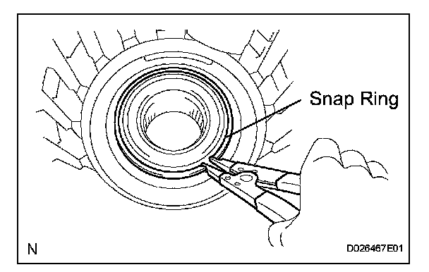
70. REMOVE TRANSFER DRIVEN PINION FRONT BEARING
(a) Using a snap ring expander, remove the snap ring.
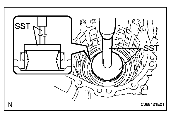
(b) Using SST and a press, remove the bearing outer race.
SST 09950-60020 (09951-00910)
71. REMOVE NO. 2 BREATHER PLUG
72. REMOVE UNDERDRIVE BRAKE RETURN SPRING SUB-ASSEMBLY
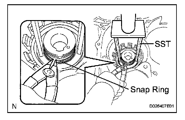
(a) Place SST on the return spring, and compress the return spring with a press.
SST 09387-00020
(b) Using a snap ring expander, remove the snap ring.
NOTICE:
^ Stop the press when the spring seat is lowered 1 to 2 mm (0.039 to 0.078 in.) from the snap ring groove, to prevent the spring seat from being deformed.
^ Do not expand the snap ring excessively.
73. INSPECT UNDERDRIVE BRAKE RETURN SPRING SUB-ASSEMBLY
74. REMOVE UNDERDRIVE BRAKE PISTON
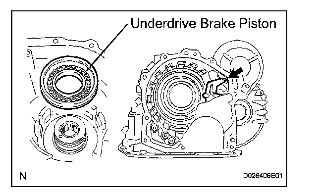
(a) Apply compressed air (392 kPa, 4.0 kgf/cm2, 57 psi) to the transaxle case to remove the underdrive brake piston.
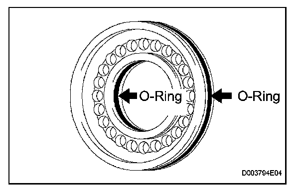
(b) Remove the 2 O-rings from the underdrive brake piston.
75. REMOVE NEEDLE ROLLER BEARING
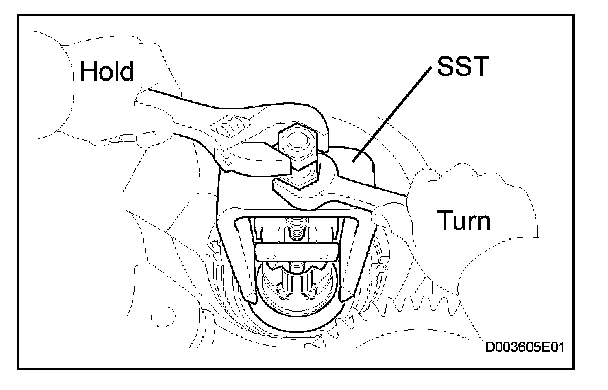
(a) Using SST remove the needle roller bearing from the transaxle case.
SST 09387-00041 (09387-01010, 09387-01030, 09387-01040)
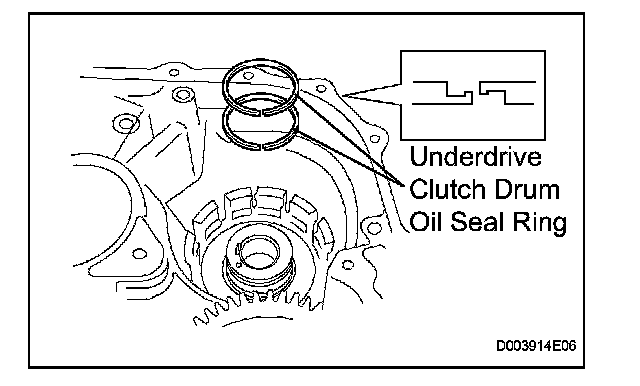
76. REMOVE UNDERDRIVE CLUTCH DRUM OIL SEAL RING
(a) Remove the 2 oil seal rings from the transaxle case.
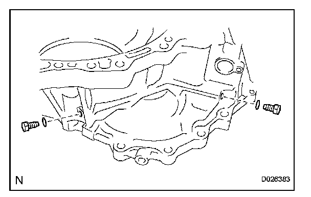
77. REMOVE NO. 1 TRANSAXLE CASE PLUG
(a) Remove the 2 No. 1 transaxle case plugs.
(b) Remove the 2 O-rings from the 2 No. 1 transaxle case plugs.
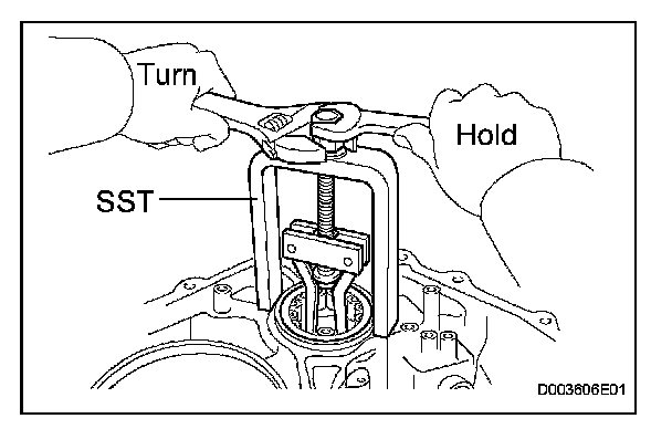
78. REMOVE UNDERDRIVE CYLINDRICAL ROLLER BEARING
(a) Using SST, remove the underdrive cylindrical roller bearing from the transaxle case.
SST 09514-35011
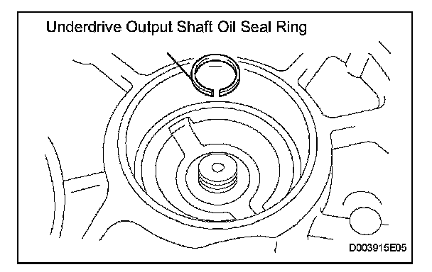
79. REMOVE UNDERDRIVE OUTPUT SHAFT OIL SEAL RING
(a) Remove the oil seal ring from the transaxle housing.
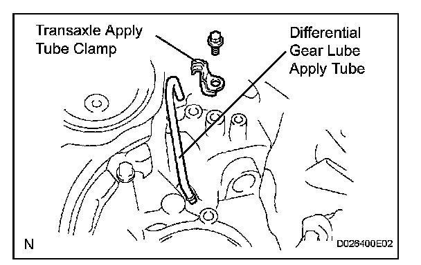
80. REMOVE DIFFERENTIAL GEAR LUBE APPLY TUBE
(a) Remove the bolt, transaxle apply tube clamp and differential gear lube apply tube from the transaxle housing.
NOTICE: Do not bend the tubes.