CAN Communication System
CAN COMMUNICATION SYSTEM:
TERMINALS OF ECU
HINT: This section describes the standard CAN values for all CAN related components.
1. CAN J/C (CAN RH J/C, CAN CENTER J/C)
(a) CAN RH J/C.
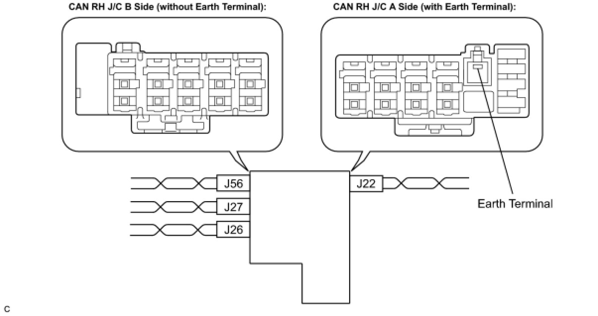
NOTICE:
- The connectors connected to the CAN J/C can be distinguished by the colors of the bus lines and the connecting side of the connector.
- The connectors can be connected to any cables on the same side.
Connector color:

Connector colors:

(b) CAN Center J/C
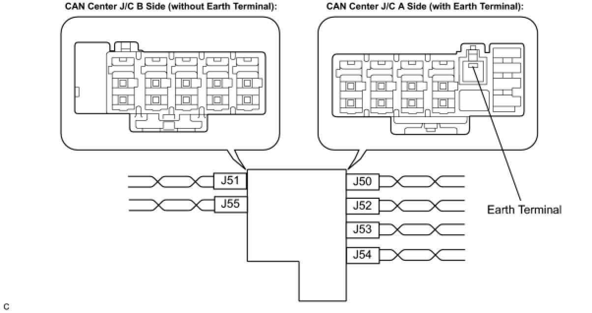
NOTICE:
- The connectors connected to the CAN J/C can be distinguished by the colors of the bus lines and the connecting side of the connector.
- The connectors can be connected to any cables on the same side.
Connector colors:

Connector colors:

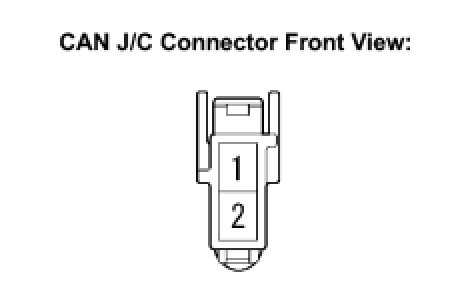
(c) The terminals of the CAN J/C connectors.
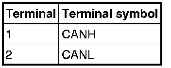
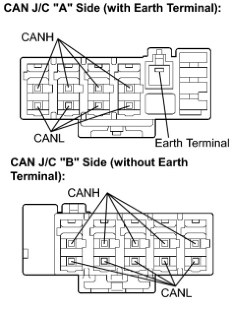
(d) Measure the resistance according to the value(s) in the table below.
Standard resistance:

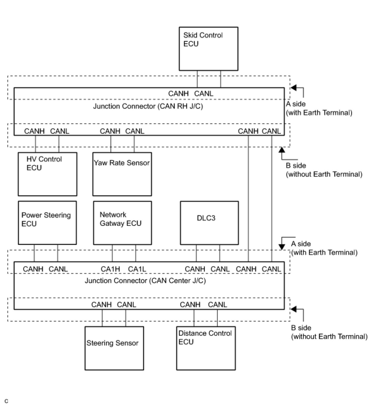
(e) Wiring diagram for identifying CAN J/C connectors.
2. DLC3
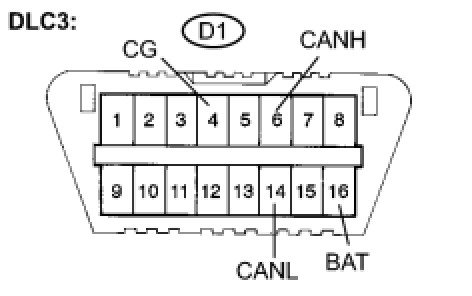
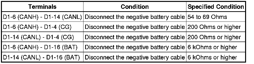
(a) Measure the resistance according to the value(s) in the table below.
Standard resistance:
3. SKID CONTROL ECU
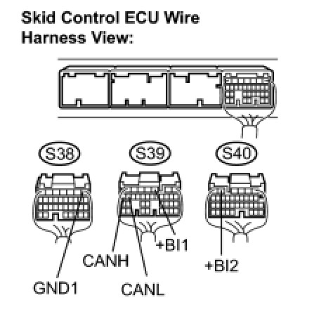
(a) Disconnect the connectors from the skid control ECU.
(b) Measure the resistance according to the value(s) in the table below.
Standard resistance:
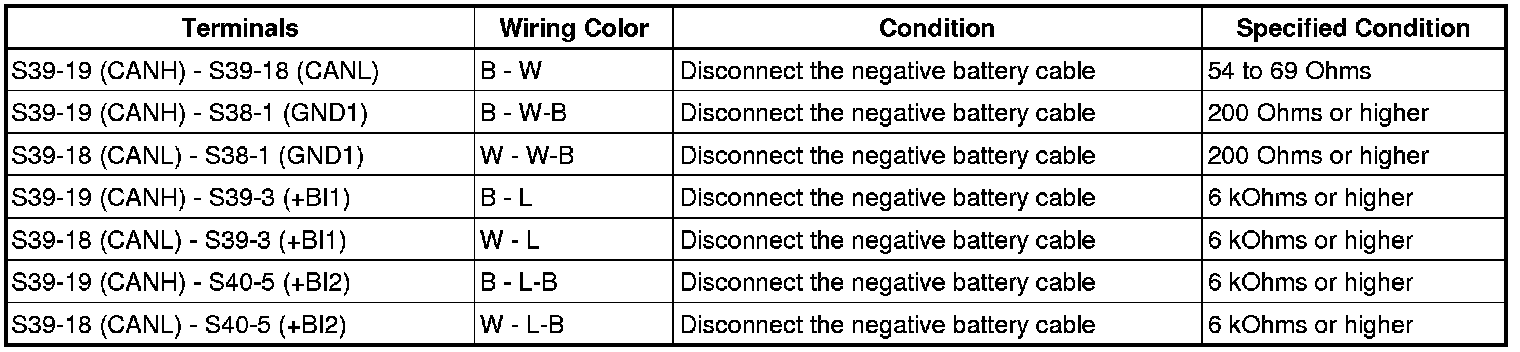
4. STEERING SENSOR
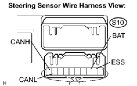
(a) Disconnect the connector from the steering sensor.
(b) Measure the resistance according to the value(s) in the table below.
Standard resistance:

5. YAW RATE SENSOR
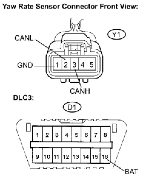
(a) Disconnect the connector from the yaw rate sensor.
(b) Measure the resistance according to the value(s) in the table below.
Standard resistance:

6. HV CONTROL ECU
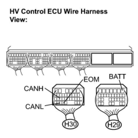
(a) Disconnect the connectors from the HV control ECU.
(b) Measure the resistance according to the value(s) in the table below.
Standard resistance:

7. POWER STEERING ECU
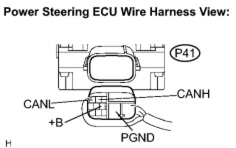
(a) Disconnect the connector from the power steering ECU.
(b) Measure the resistance according to the value(s) in the table below.
Standard resistance:

8. GATEWAY ECU
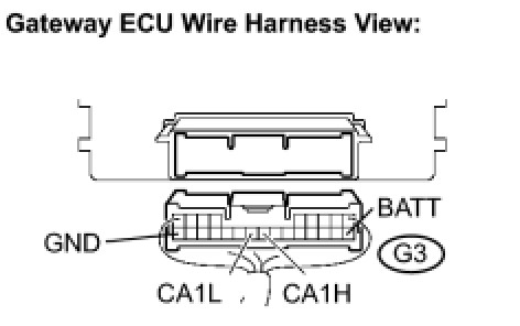
(a) Disconnect the connector from the gateway ECU.
(b) Measure the resistance according to the value(s) in the table below.
Standard resistance:

9. DISTANCE CONTROL ECU
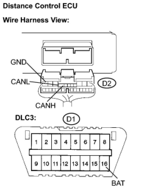
(a) Disconnect the connector from the distance control ECU.
(b) Measure the resistance according to the value(s) in the table below.
Standard resistance:
