Part 2
NETWORKING: CAN COMMUNICATION SYSTEM: DIAGNOSIS SYSTEM
For vehicles with a pre-collision system.
HINT
The millimeter wave radar sensor assembly is connected to the CAN communication system but CAN communication DTCs are not output.
(aa) LANE RECOGNITION CAMERA SENSOR ASSEMBLY
For vehicles with a lane departure alert system.
HINT
The lane recognition camera sensor assembly is connected to the CAN communication system but CAN communication DTCs are not output.
(ab) DRIVER MONITOR ECU ASSEMBLY
For vehicles with a driver monitor camera.
HINT
The driver monitor ECU assembly is connected to the CAN communication system but CAN communication DTCs are not output.
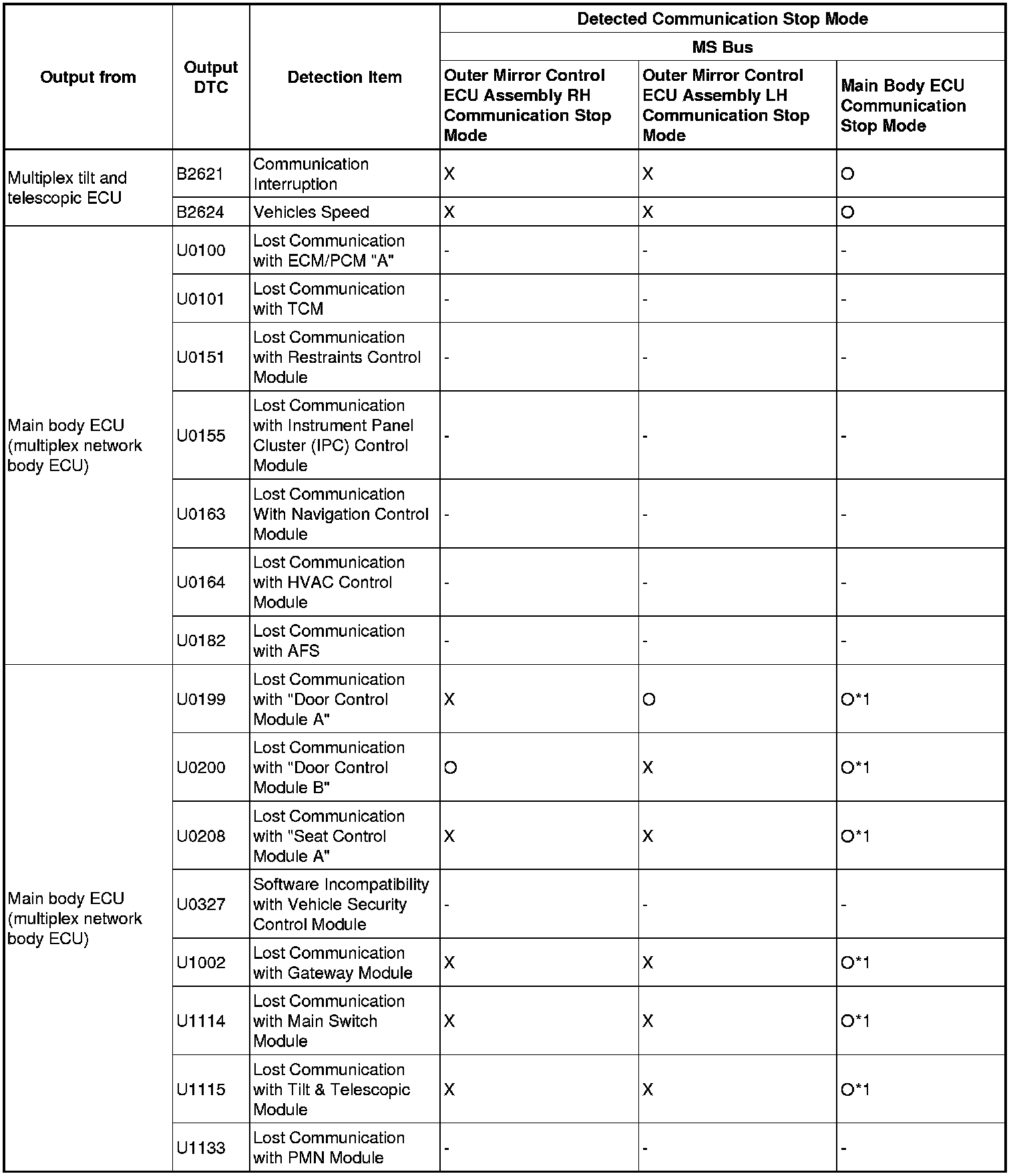
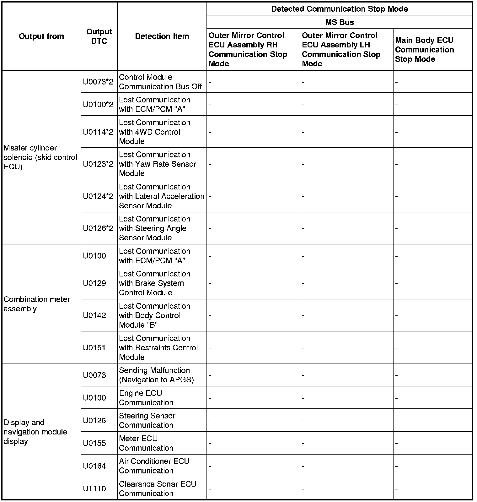
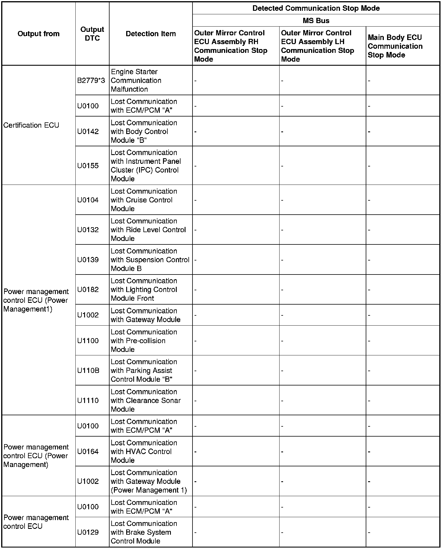
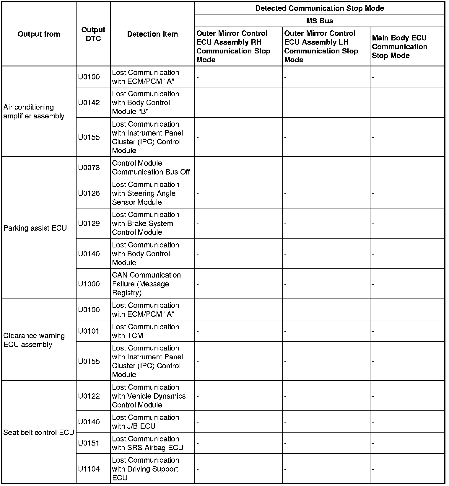
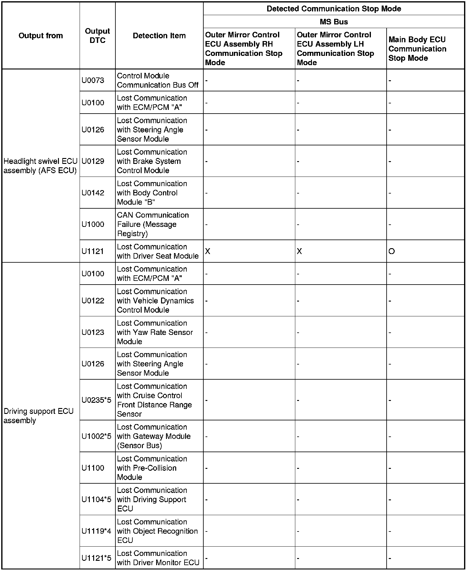
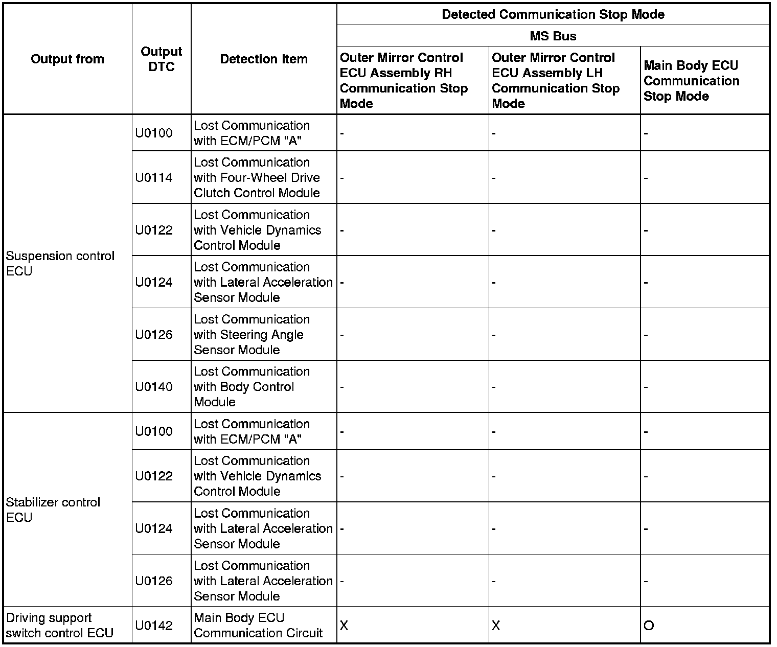
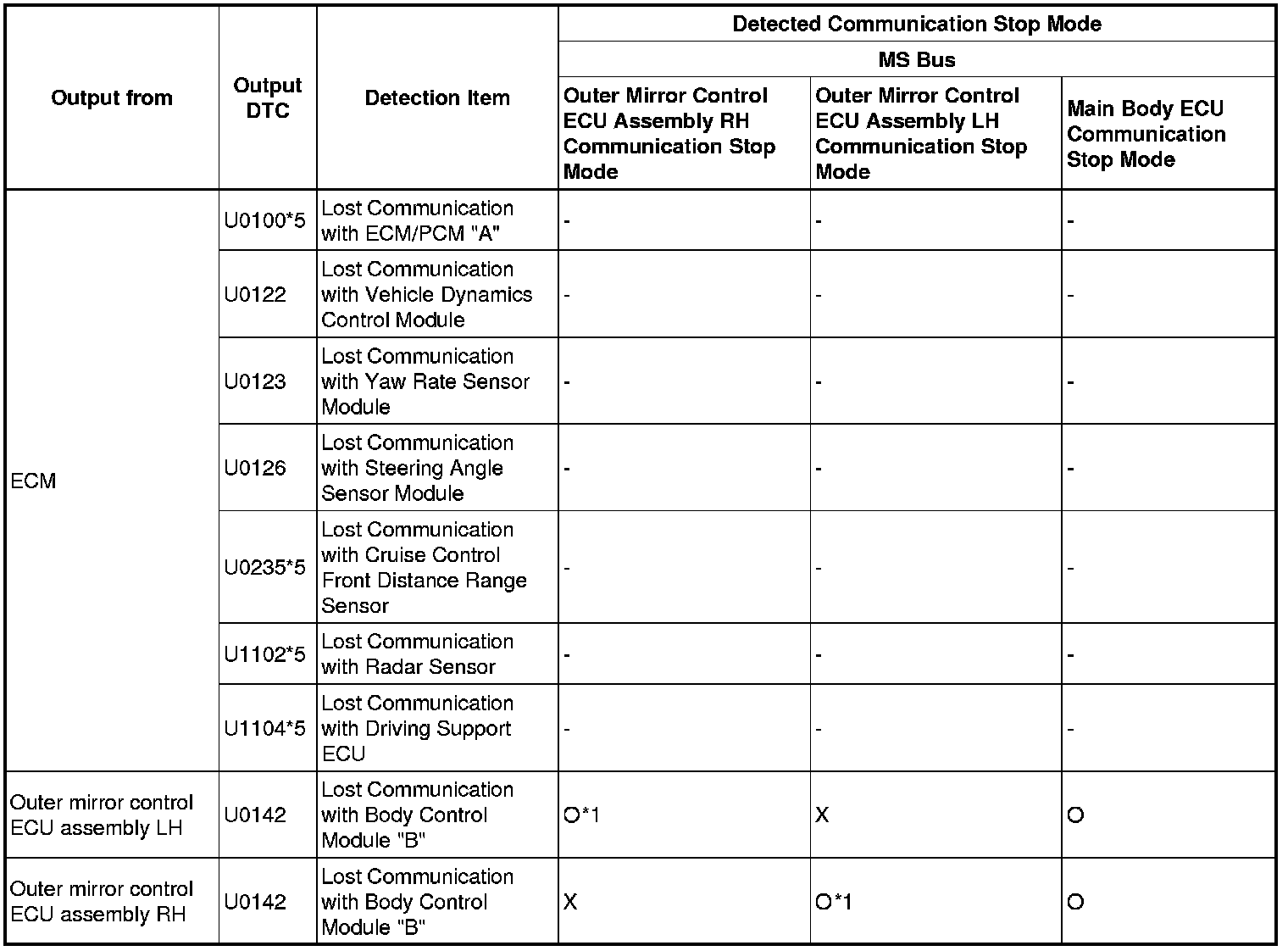
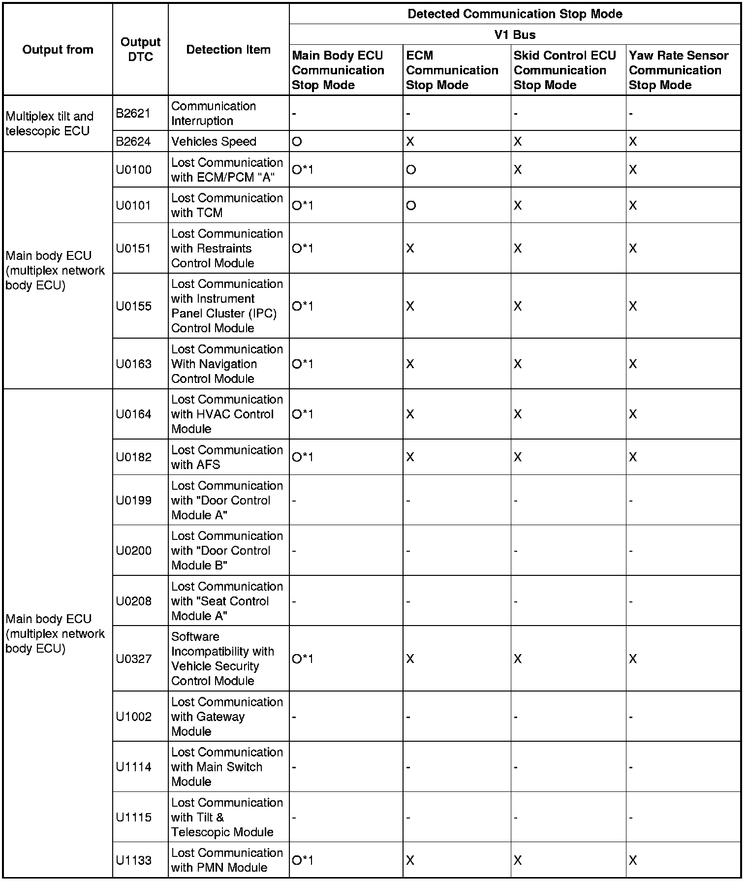
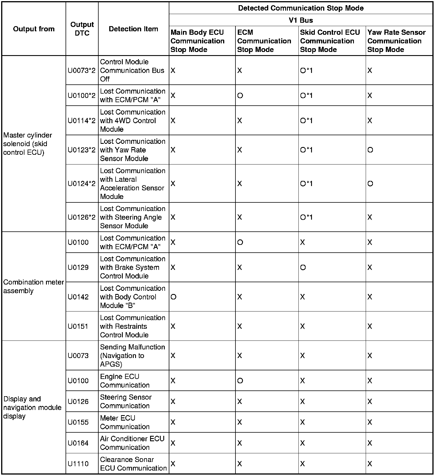
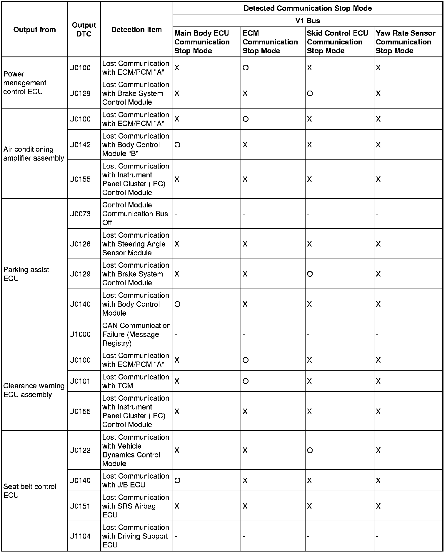
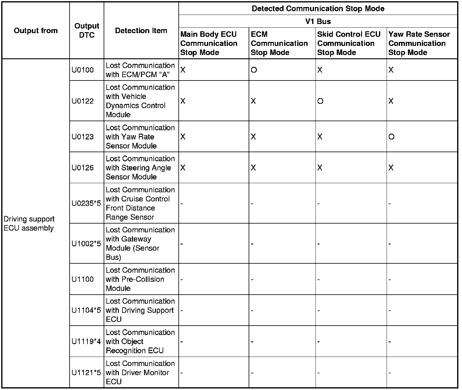
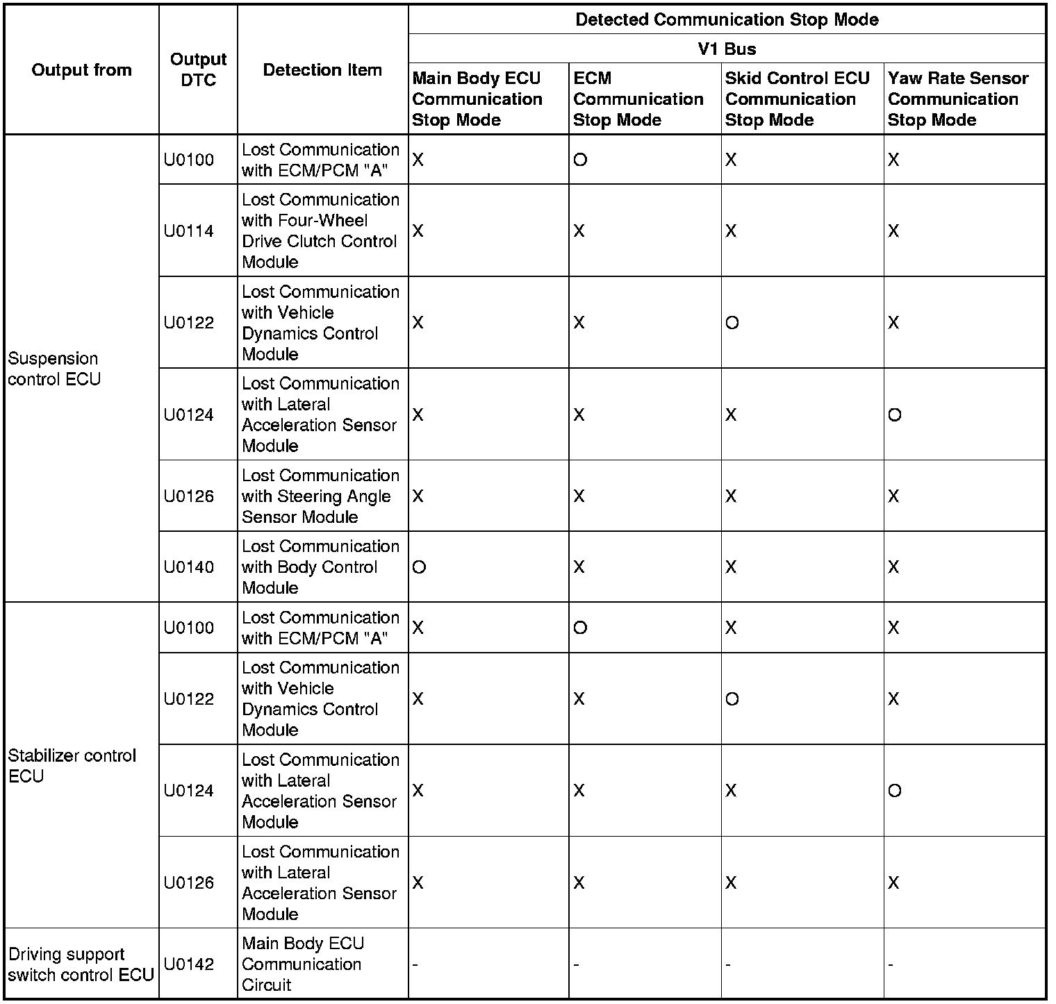
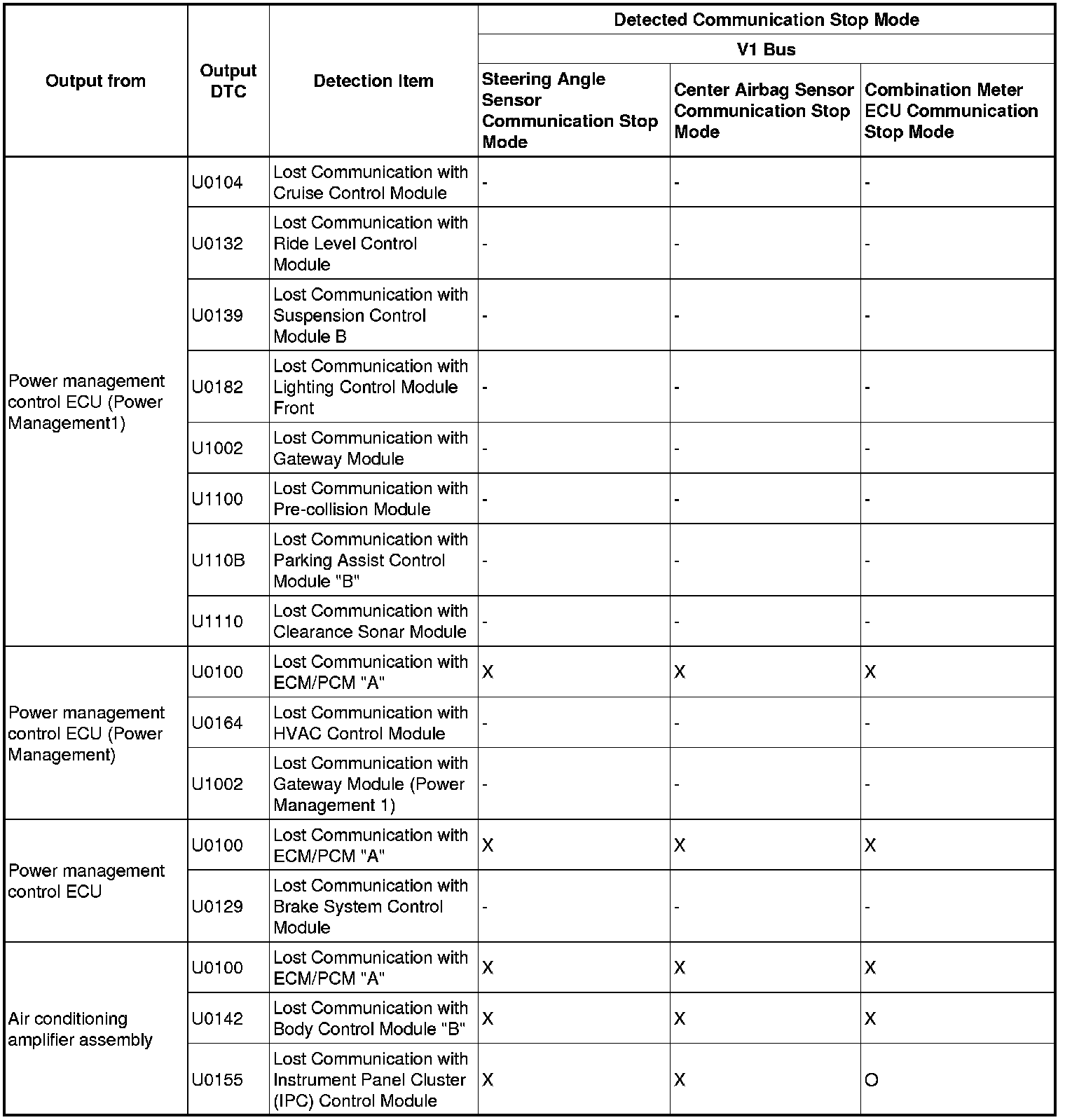
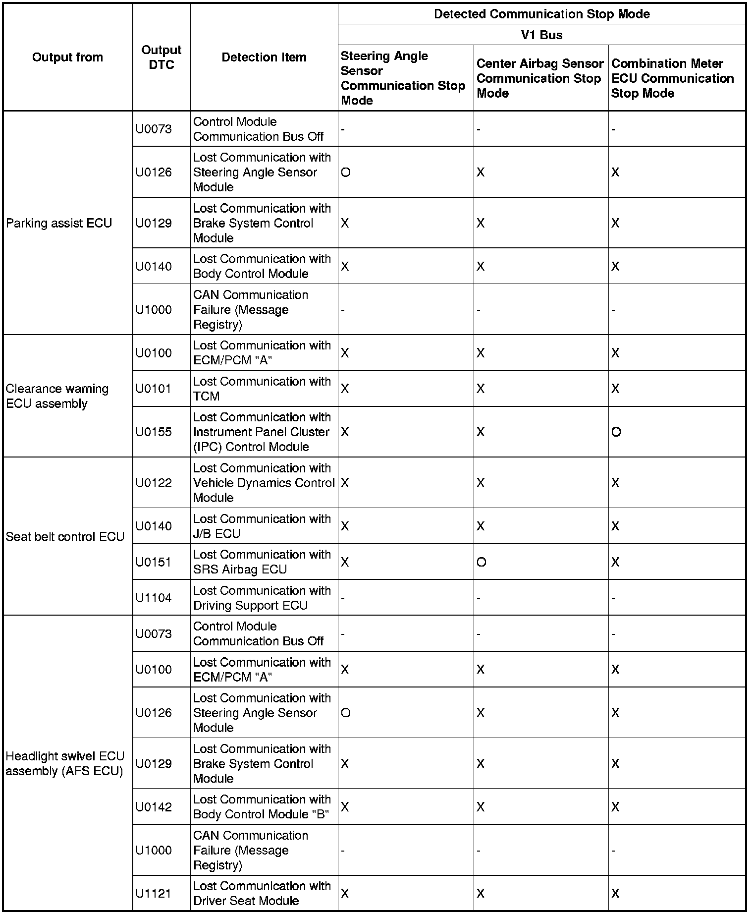
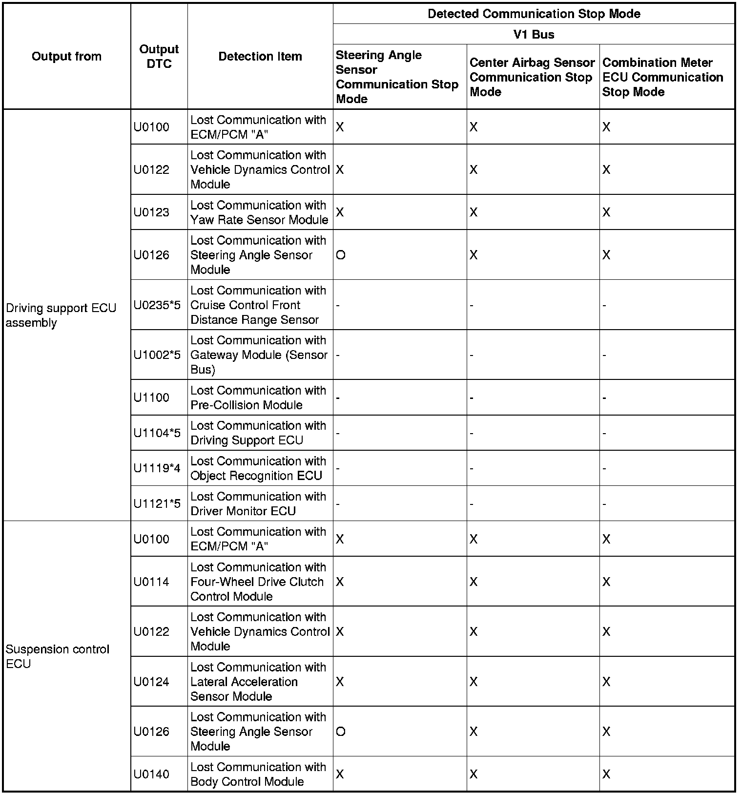
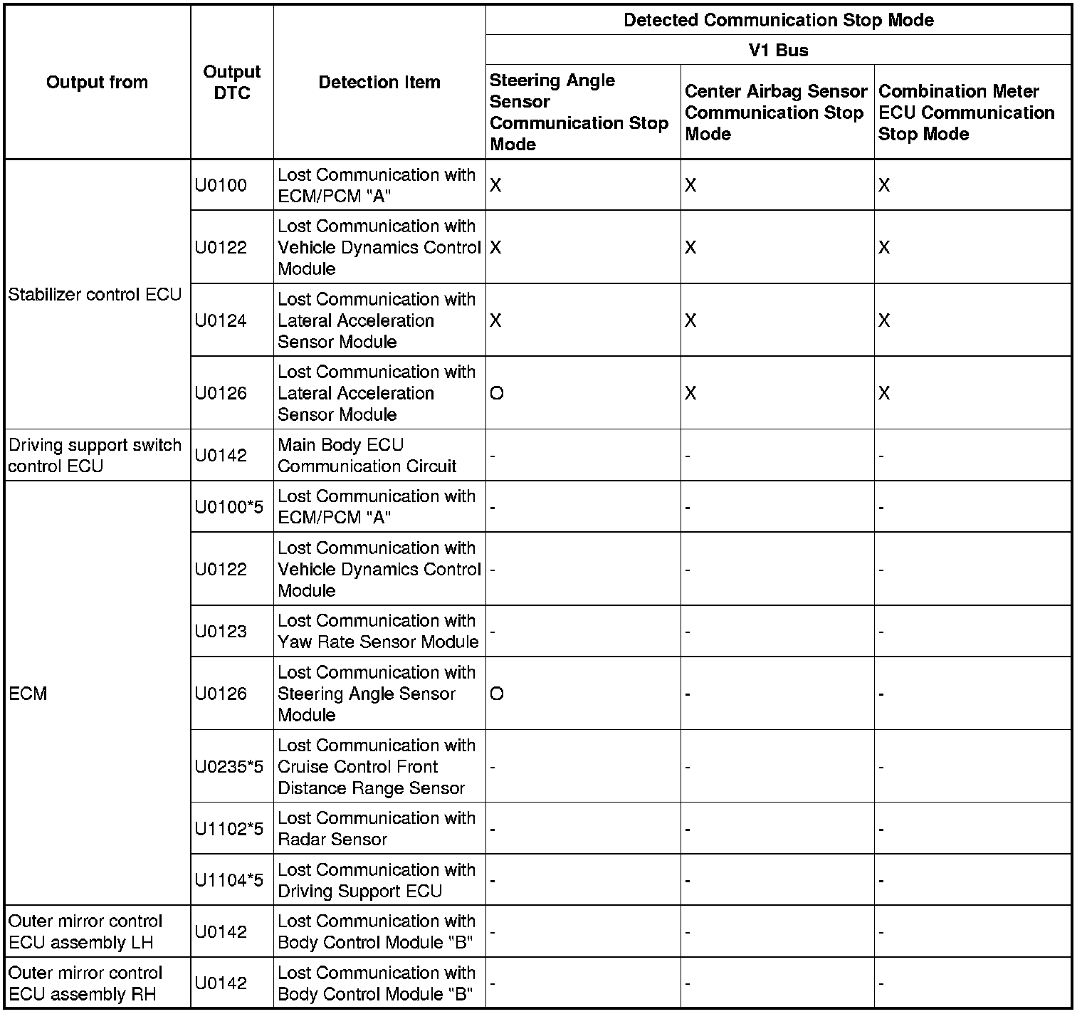
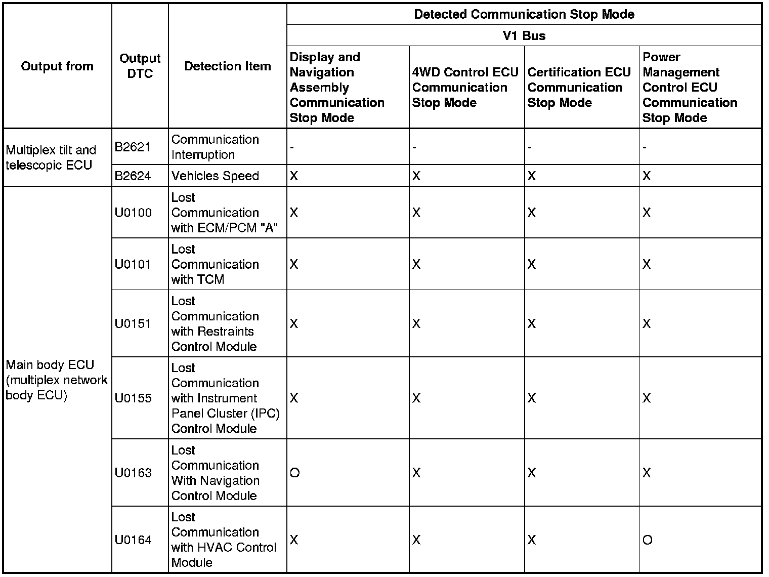
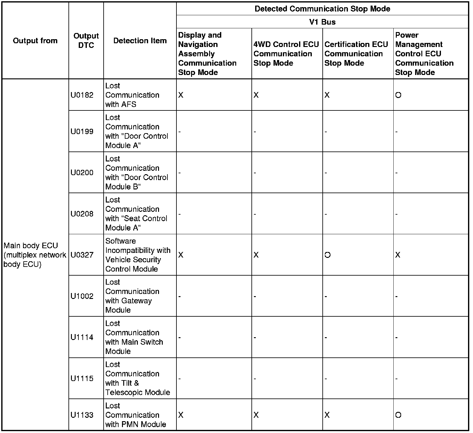
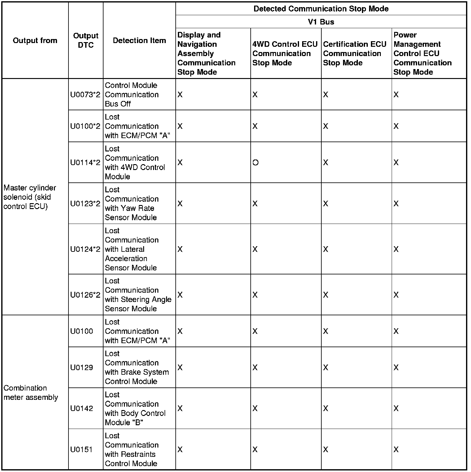
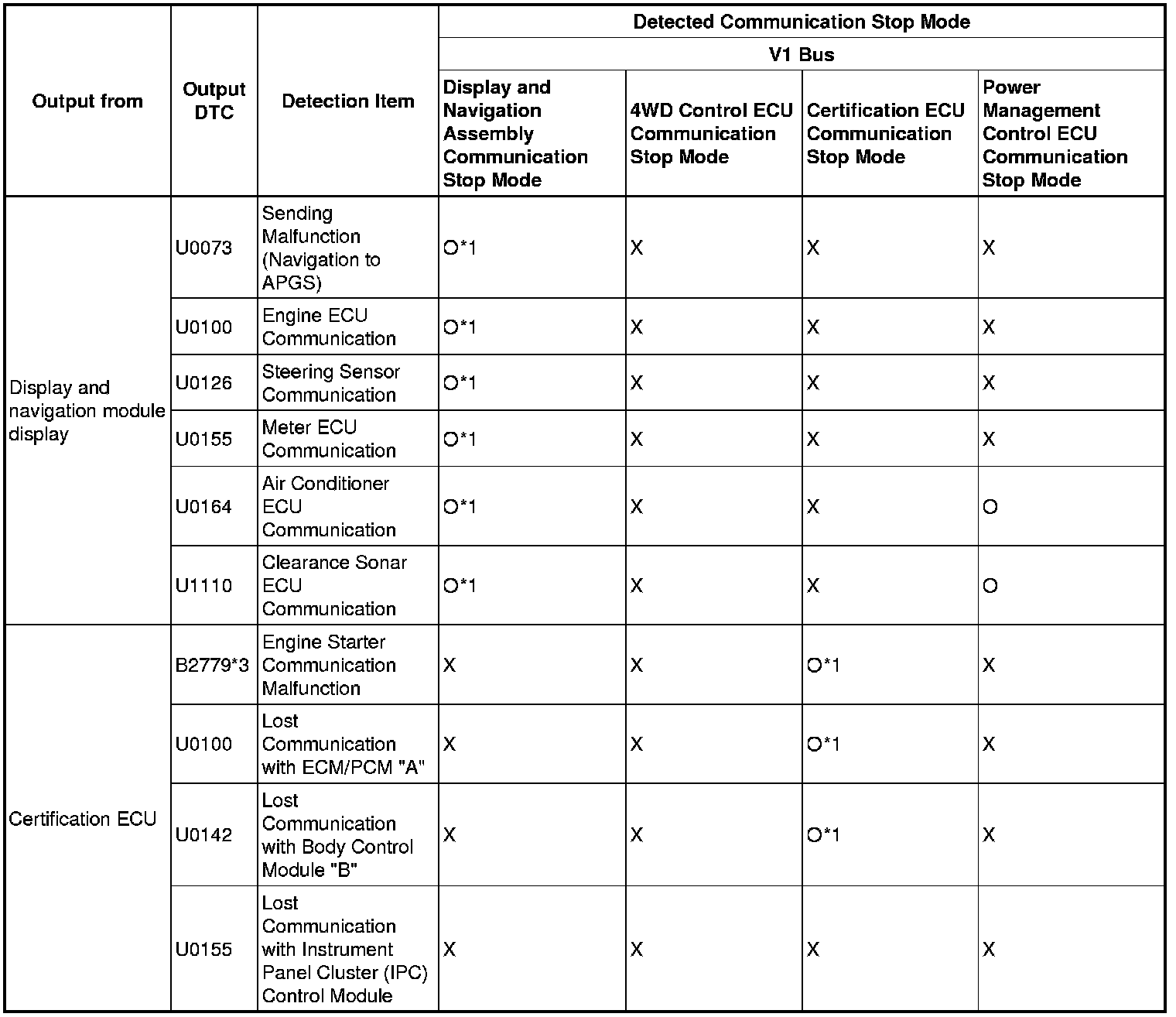
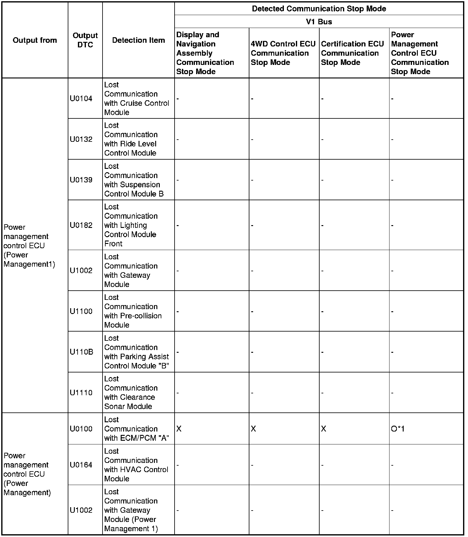
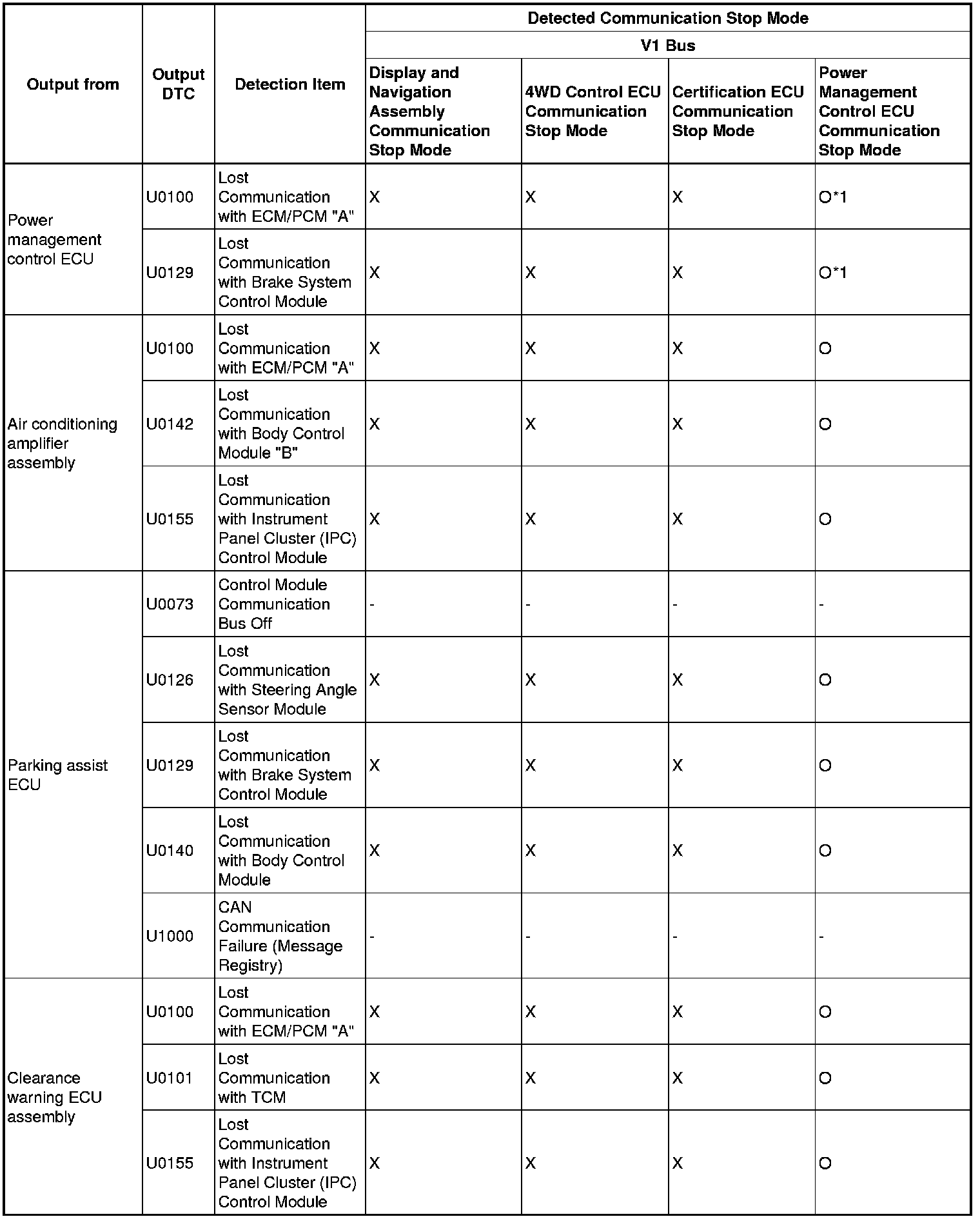
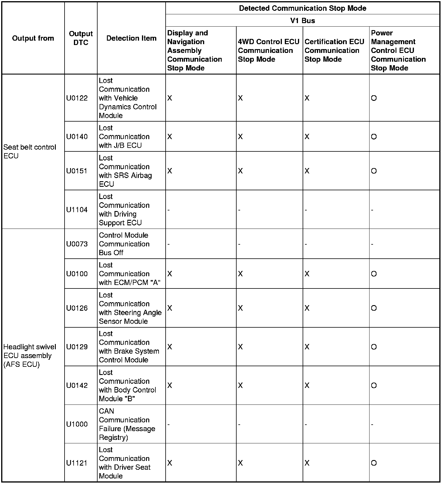
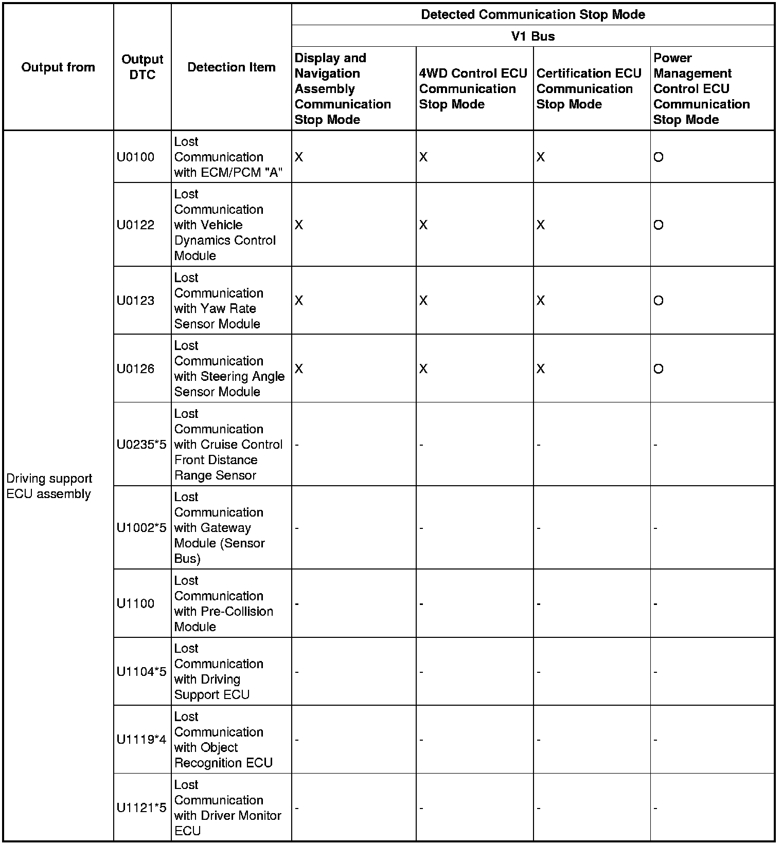
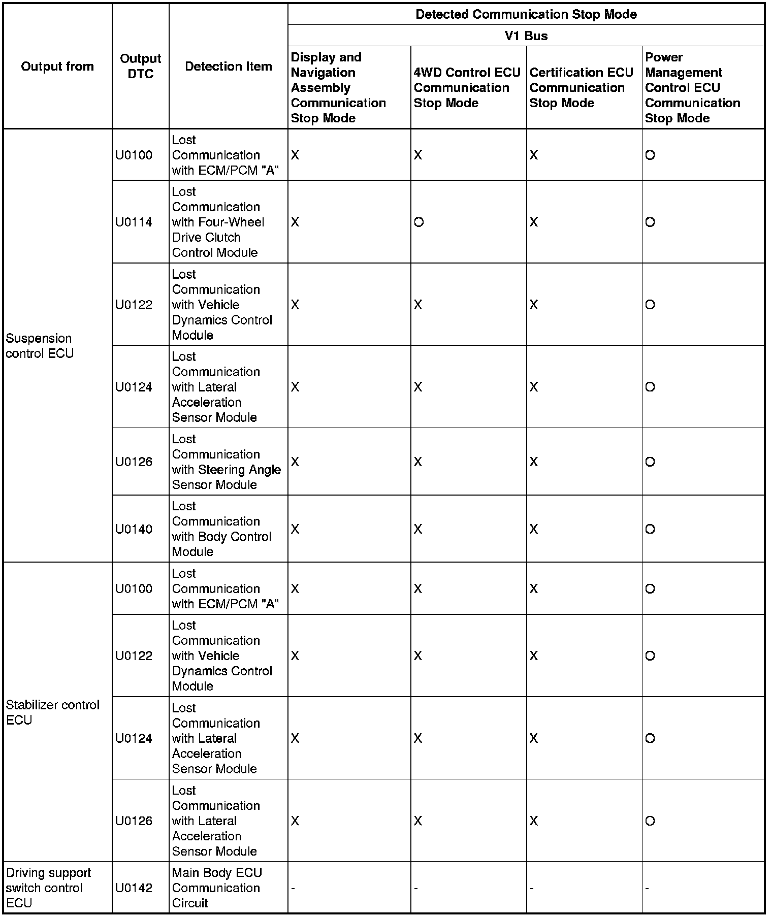
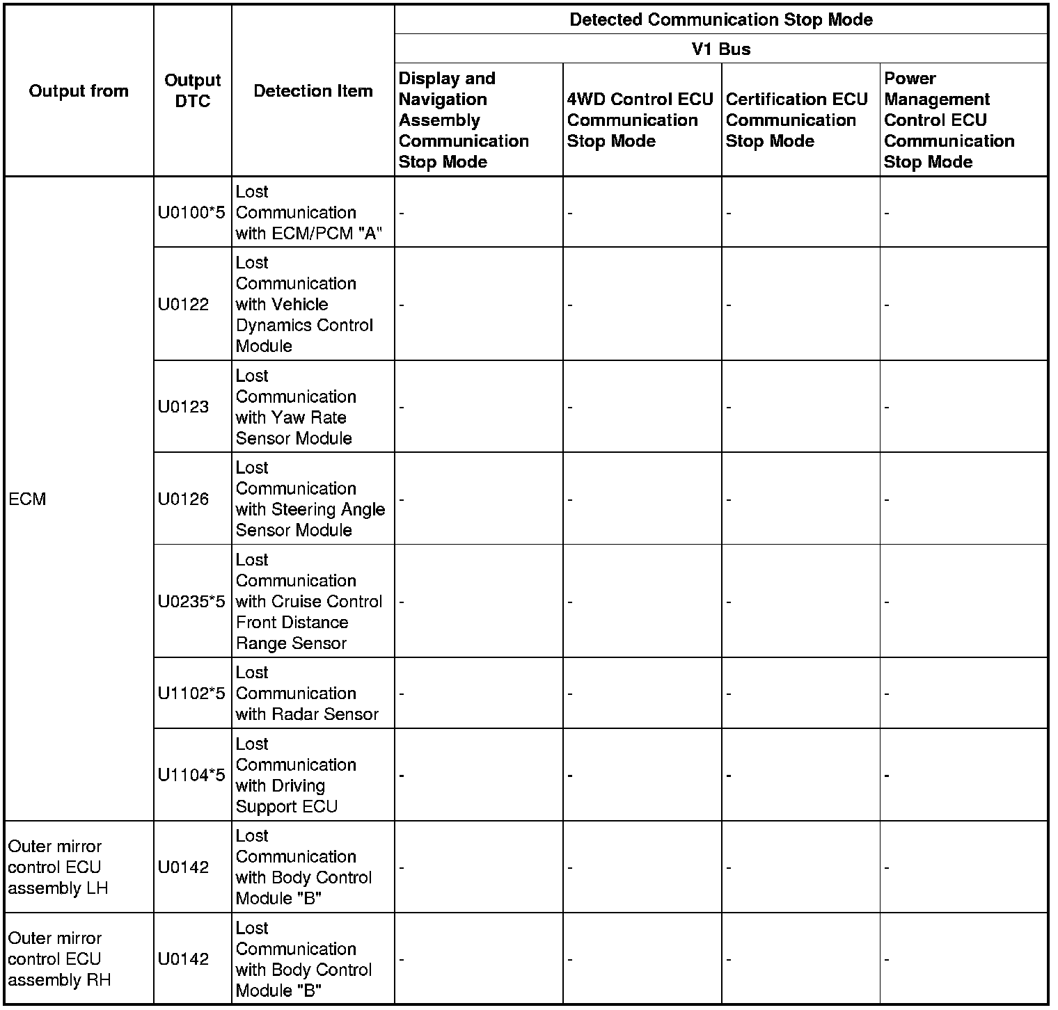
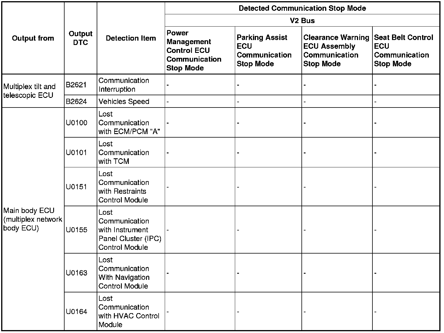
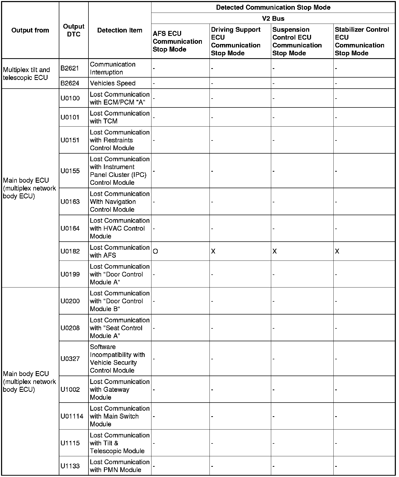
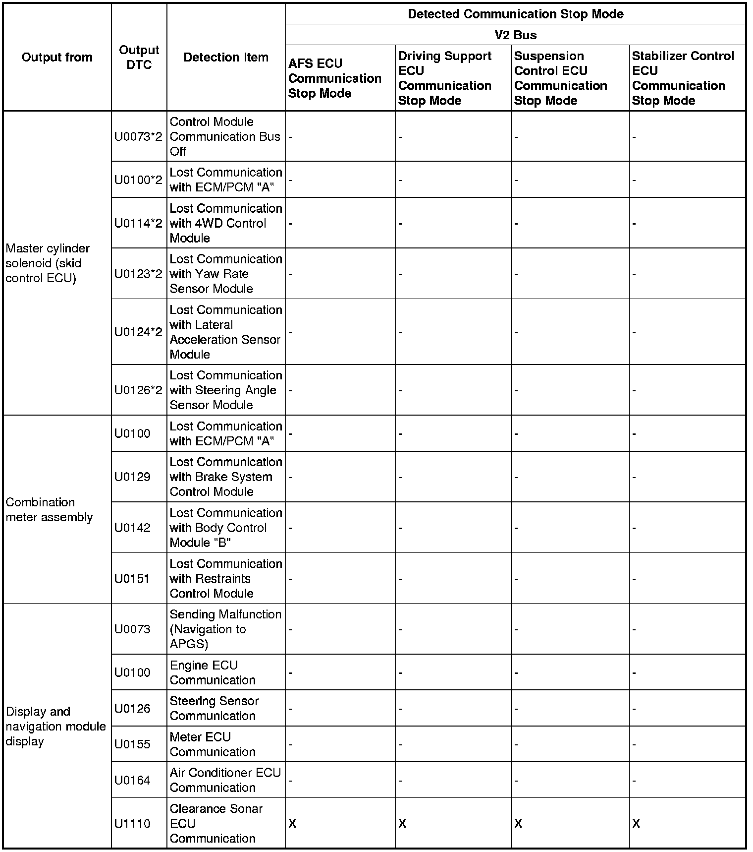
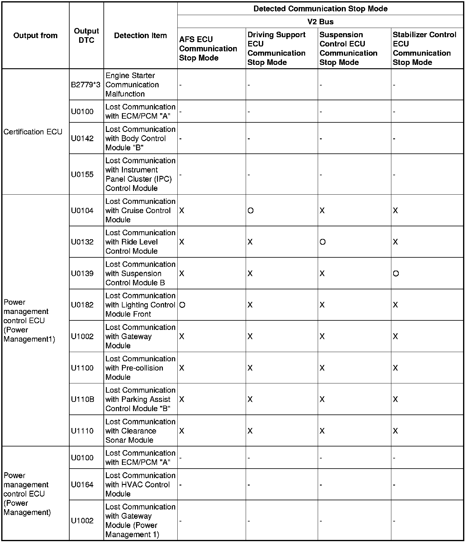
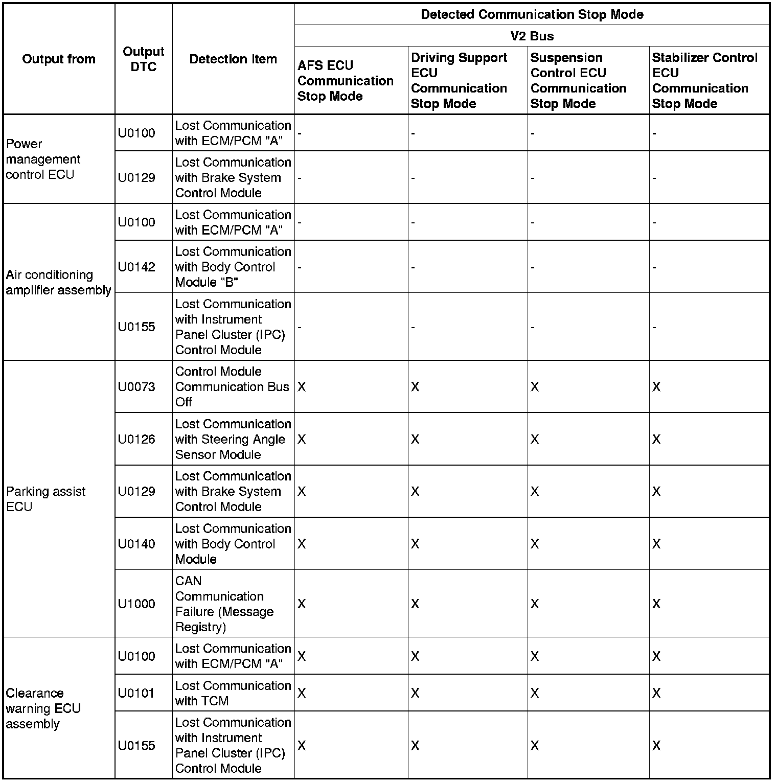
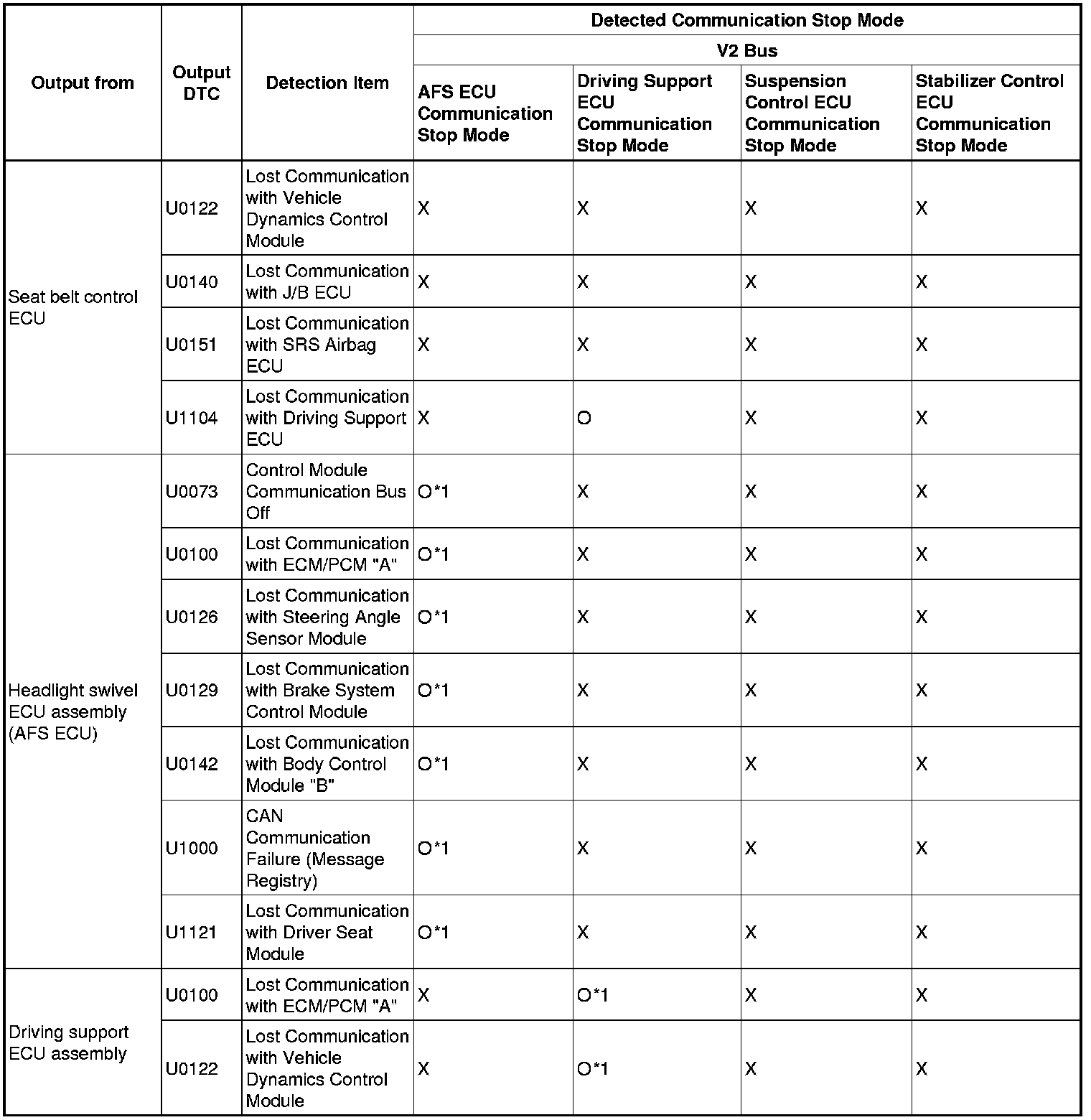
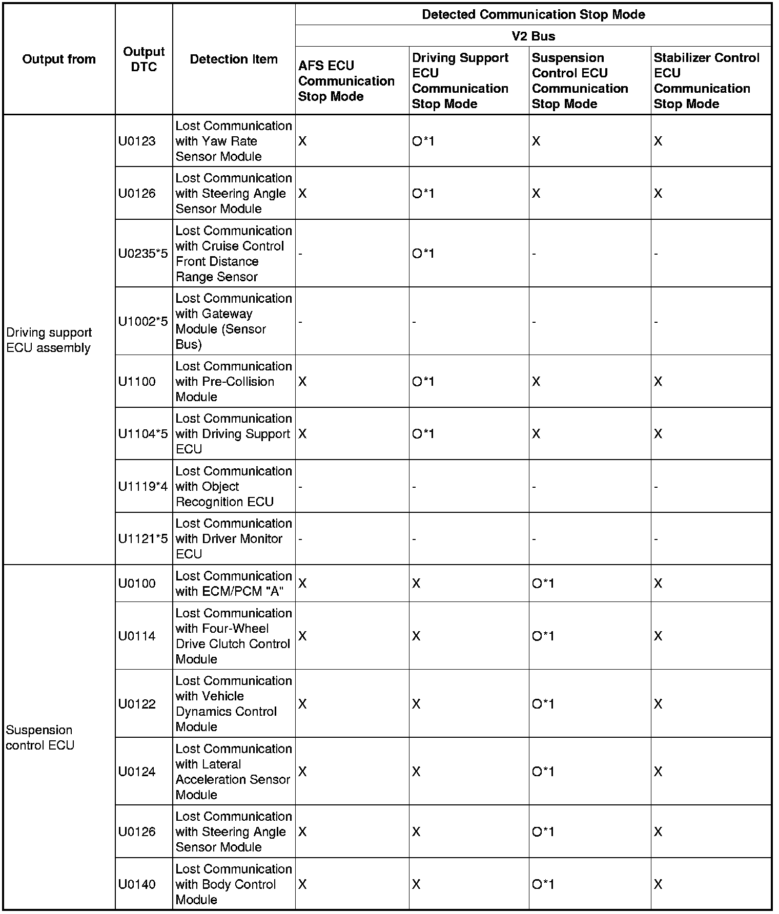
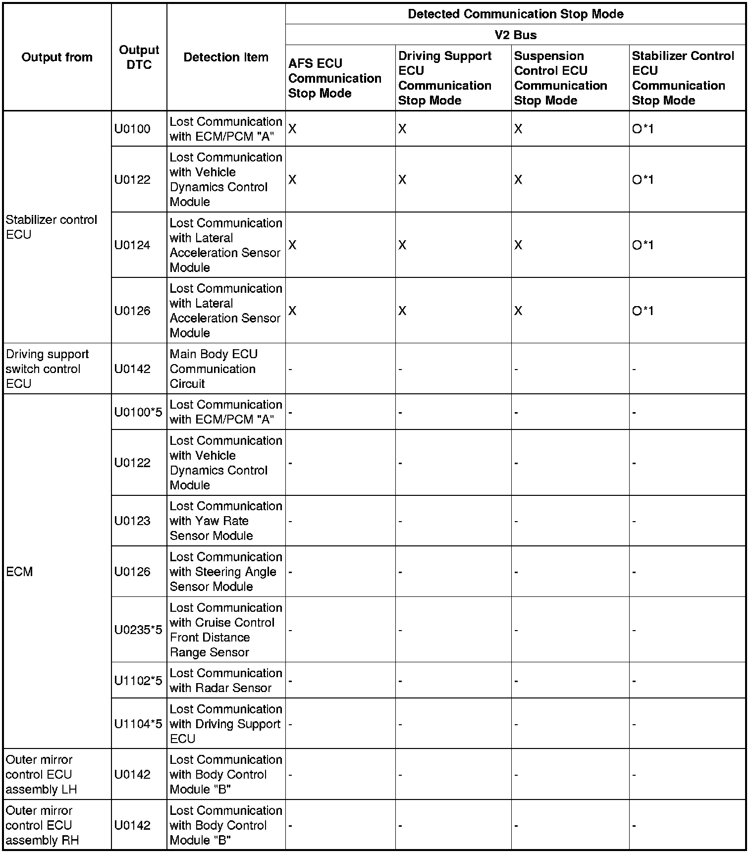
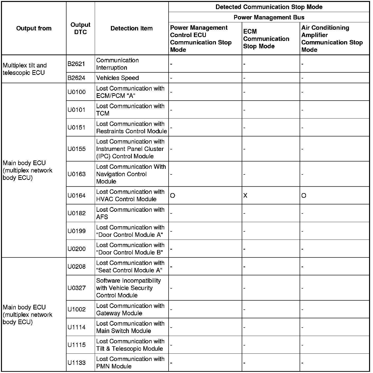
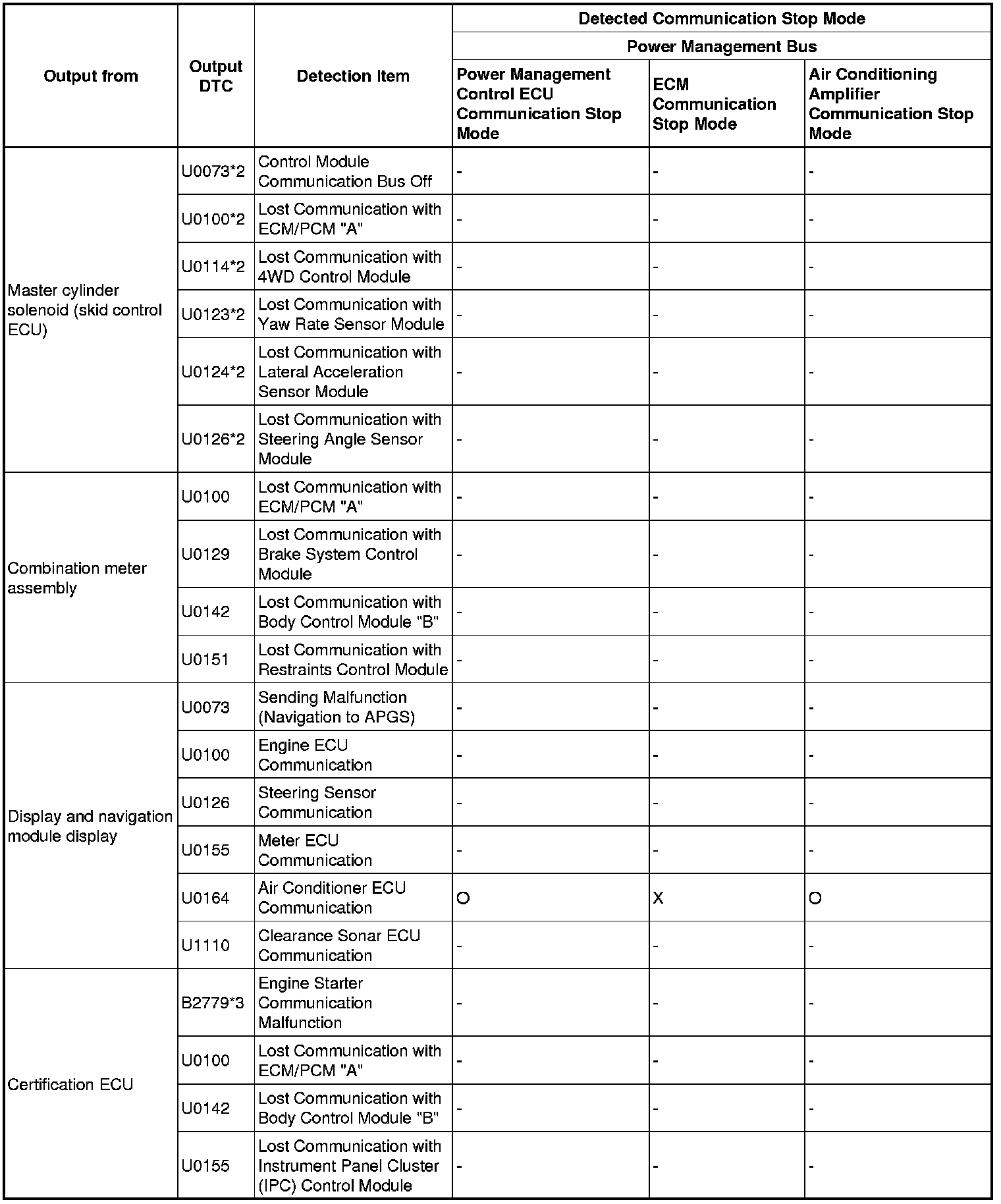
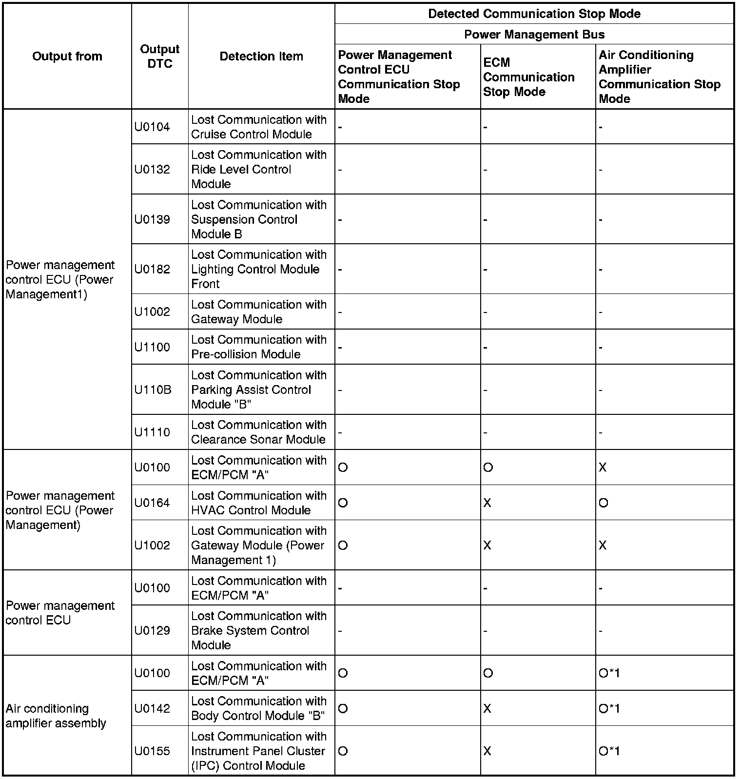
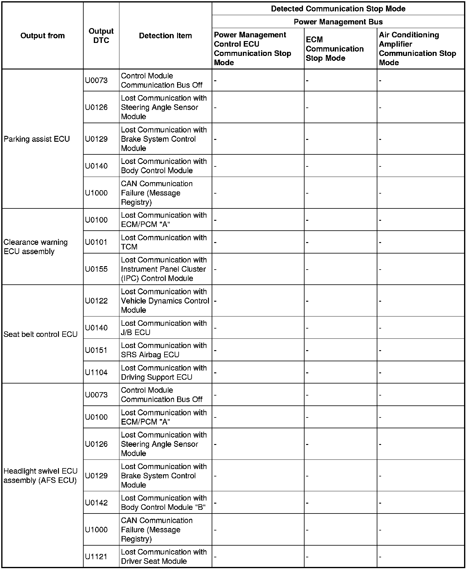
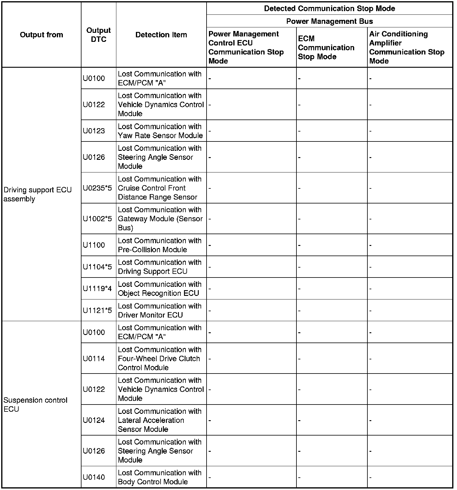
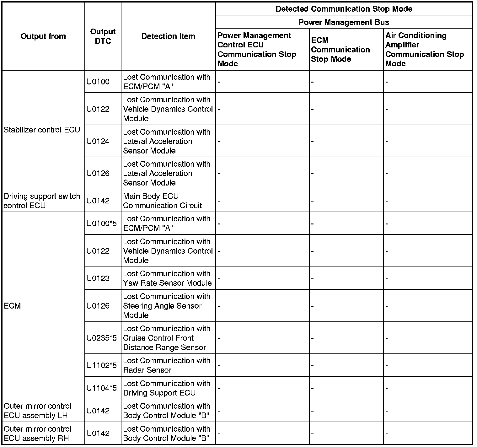
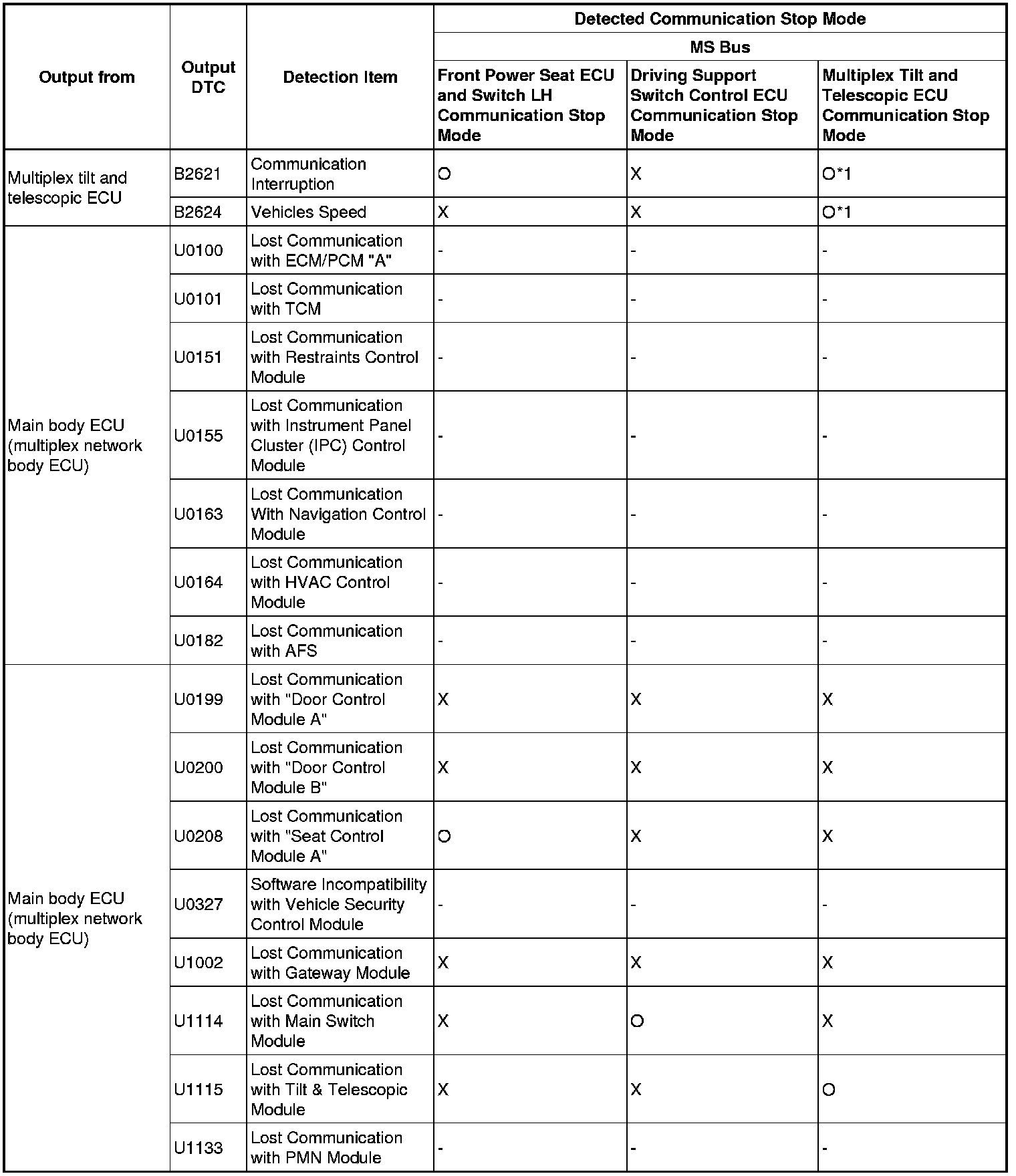
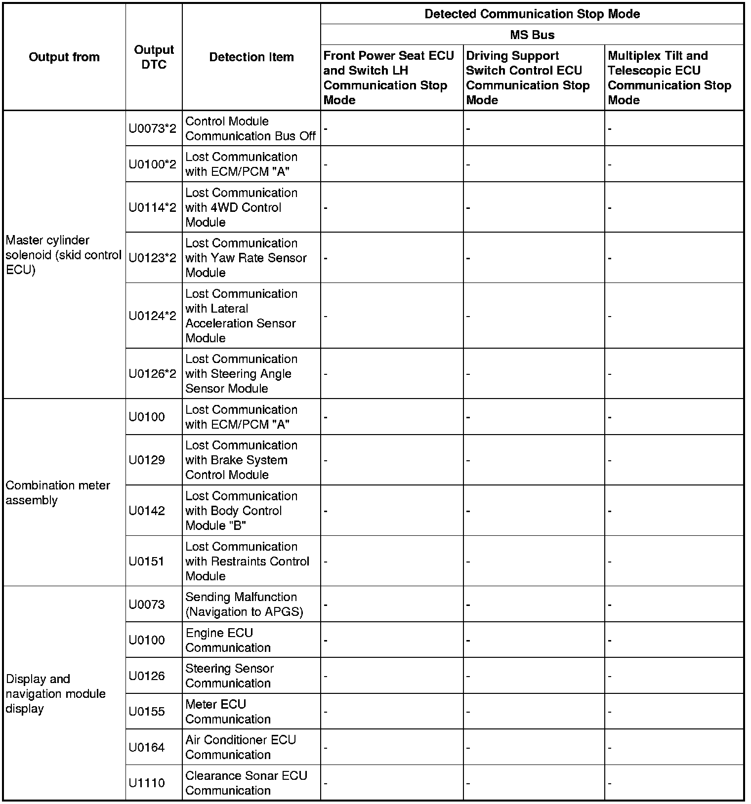
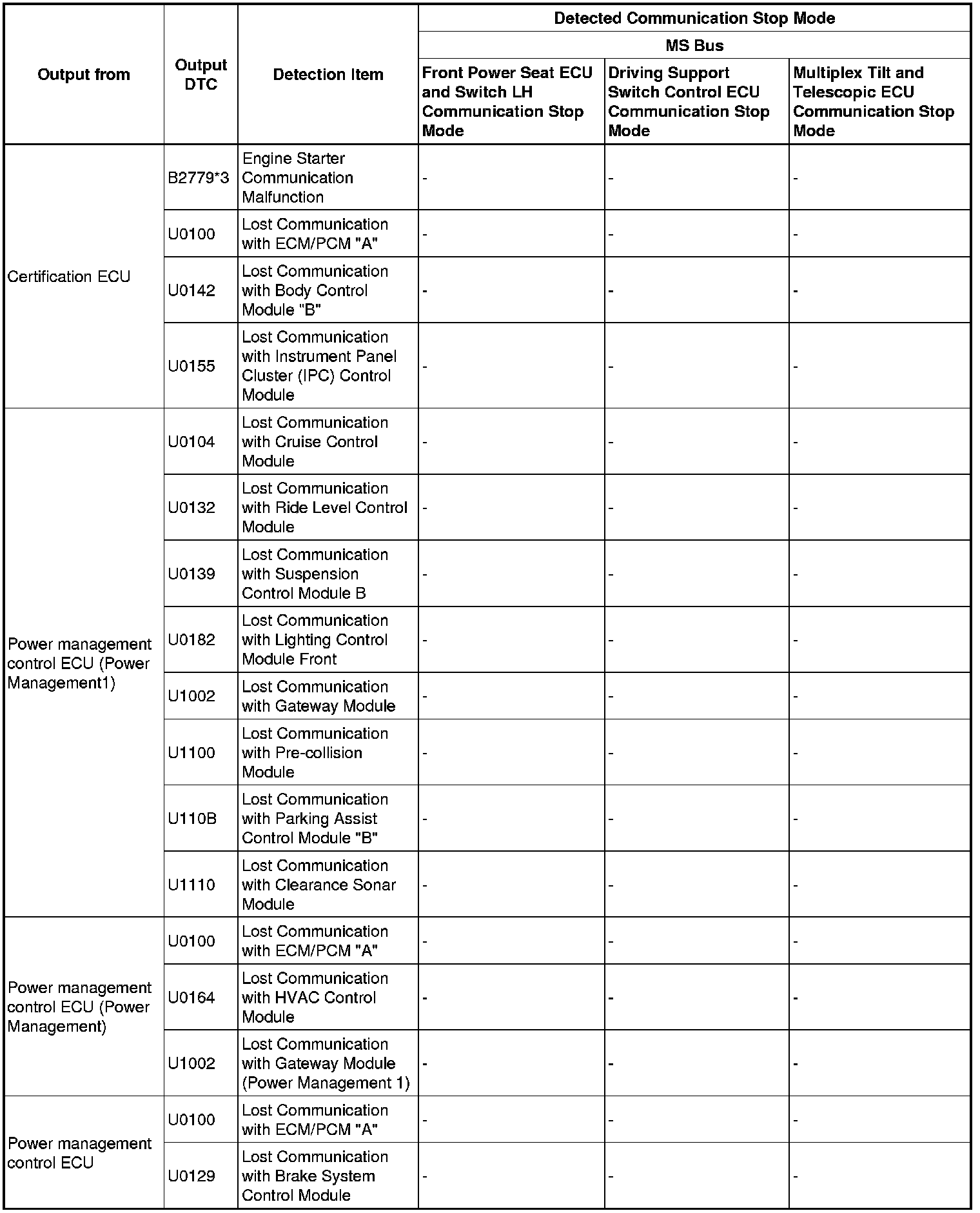
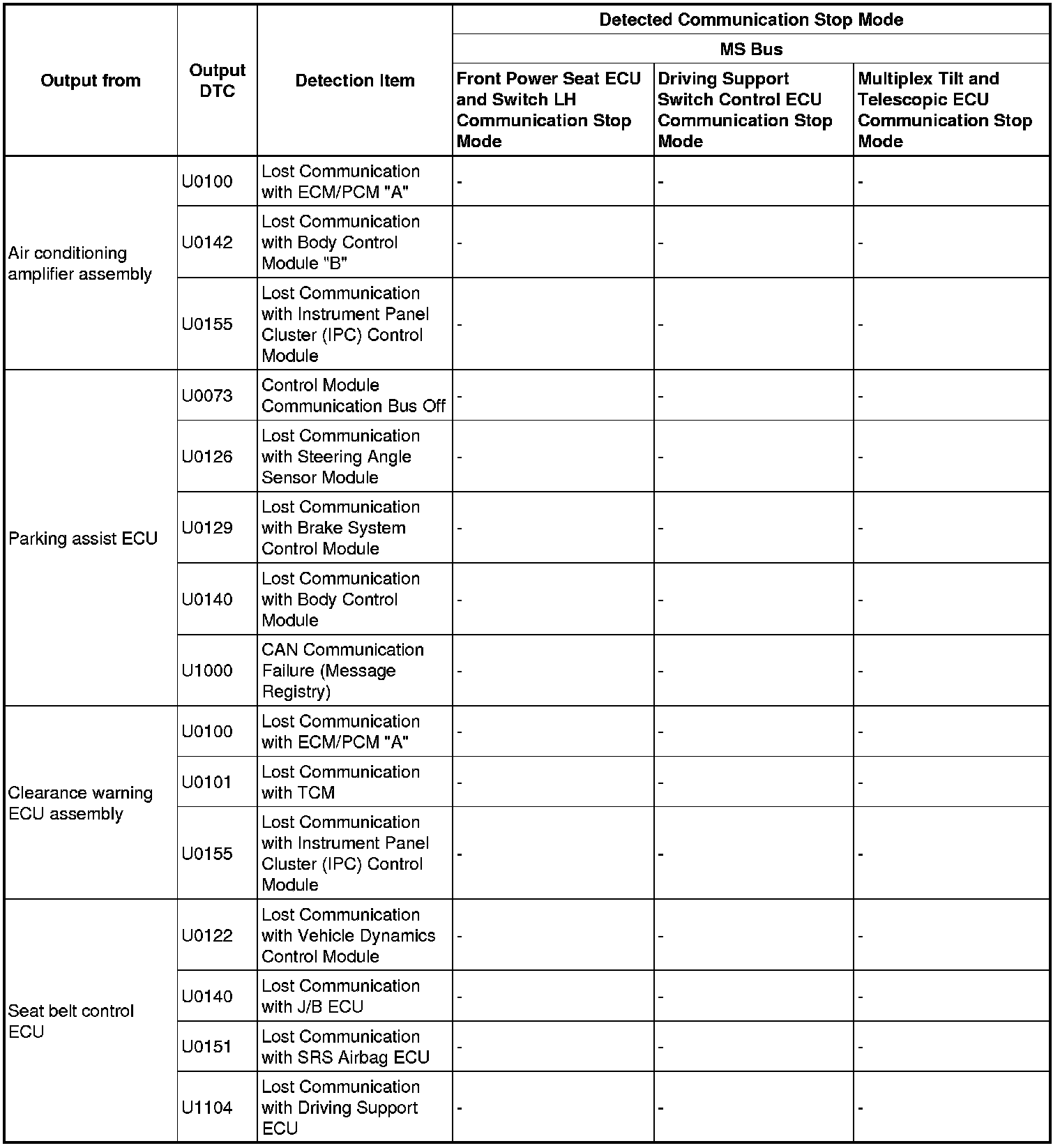
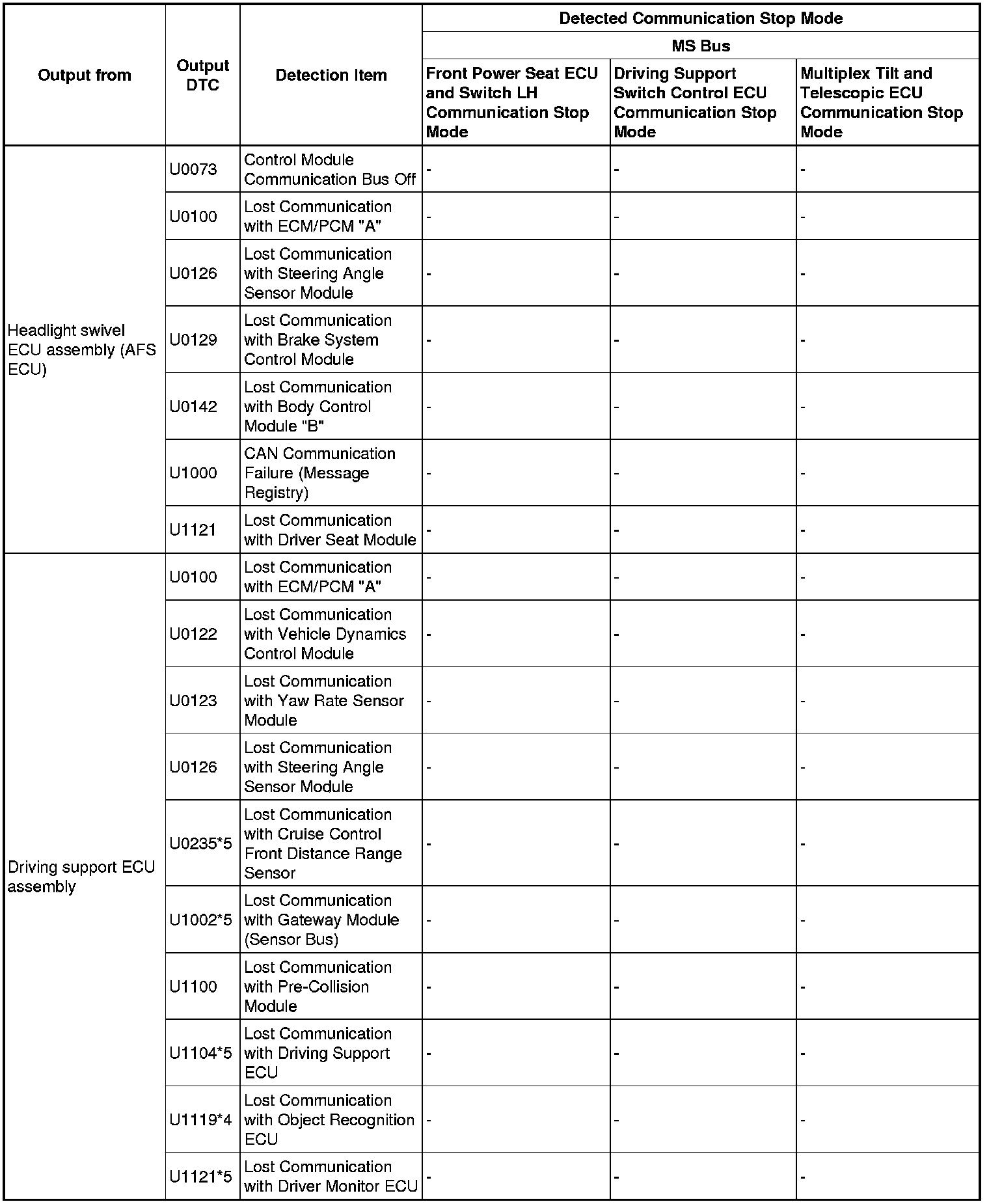
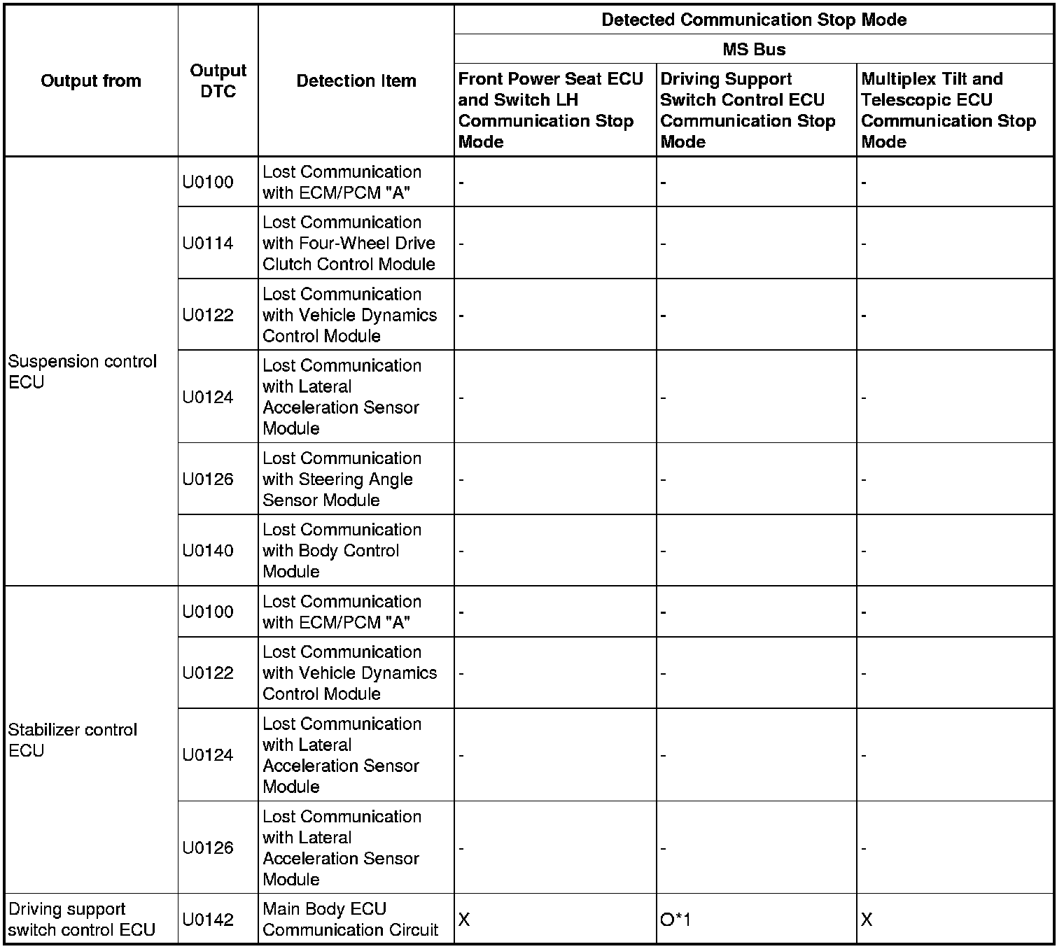
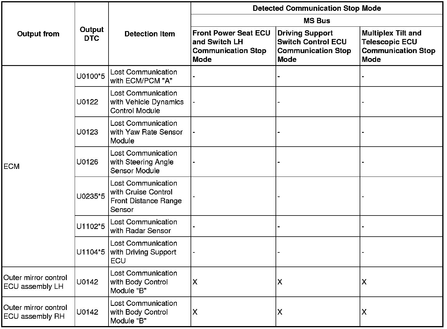
4. DTC COMBINATION TABLE
HINT
* o: Stored.
* X: When one side of branch wire is open, storage may occur.
* -: Not stored.
* *1: Only stored when communication recovery has occurred. During communication stop, cannot be stored.
* *2: Only output while a malfunction present and the engine switch is on (IG).
* *3: Only present DTCs output.
* *4: Refer to Pre-collision System U1119.
* *5: Refer to Diagnostic Trouble Code Chart CAN Communication System.
V1 Bus Vol. 1
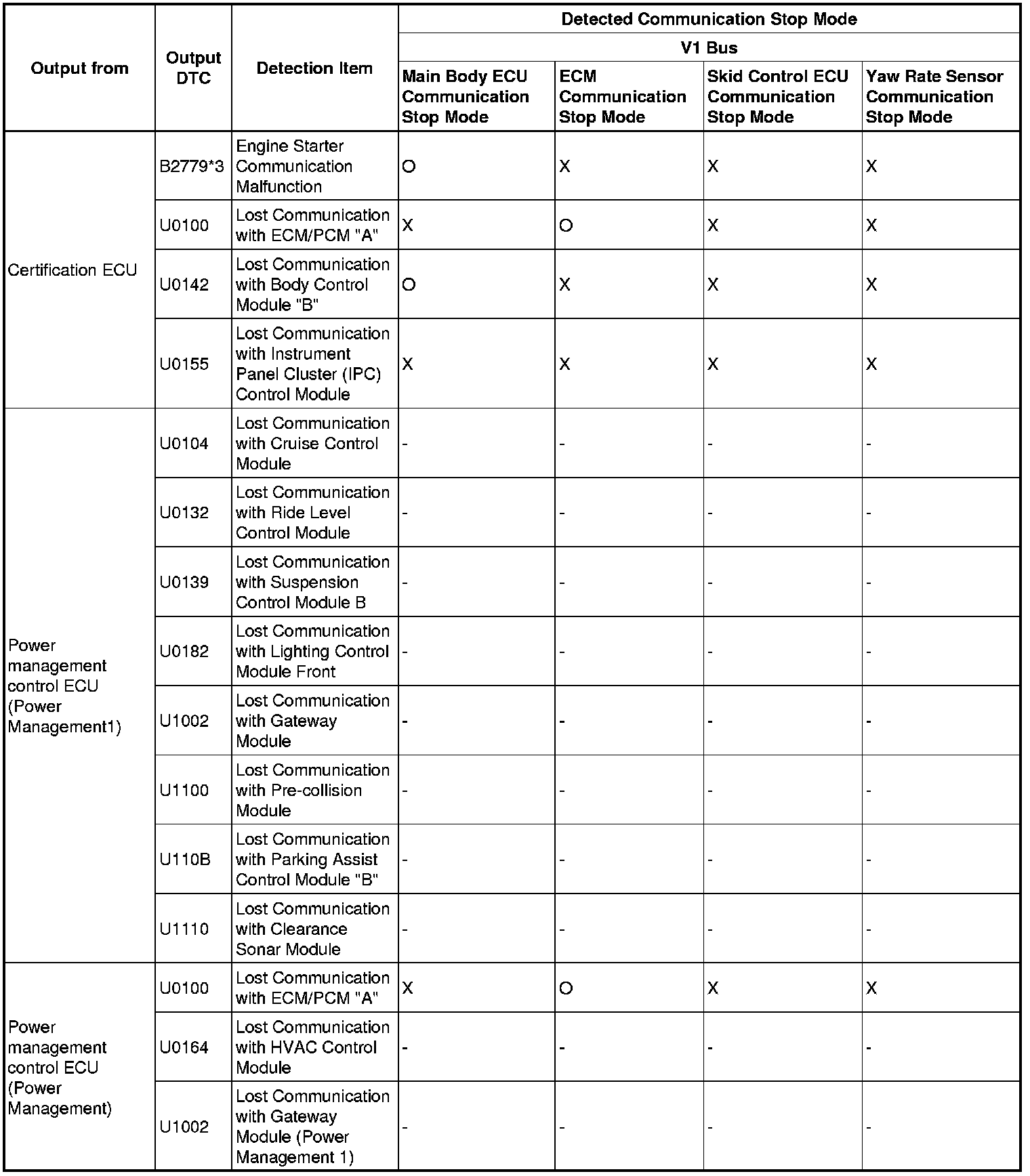

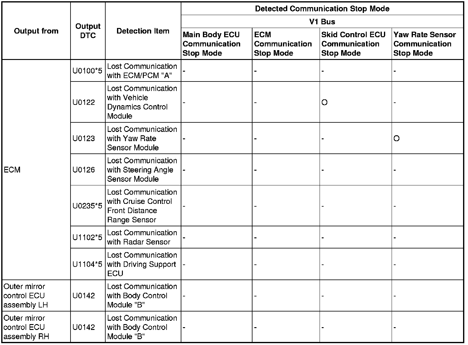
V1 Bus Vol. 2
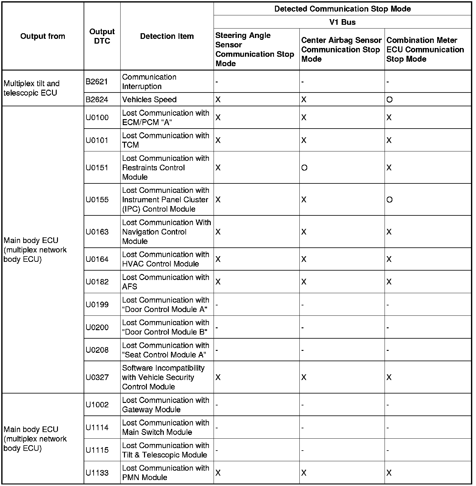
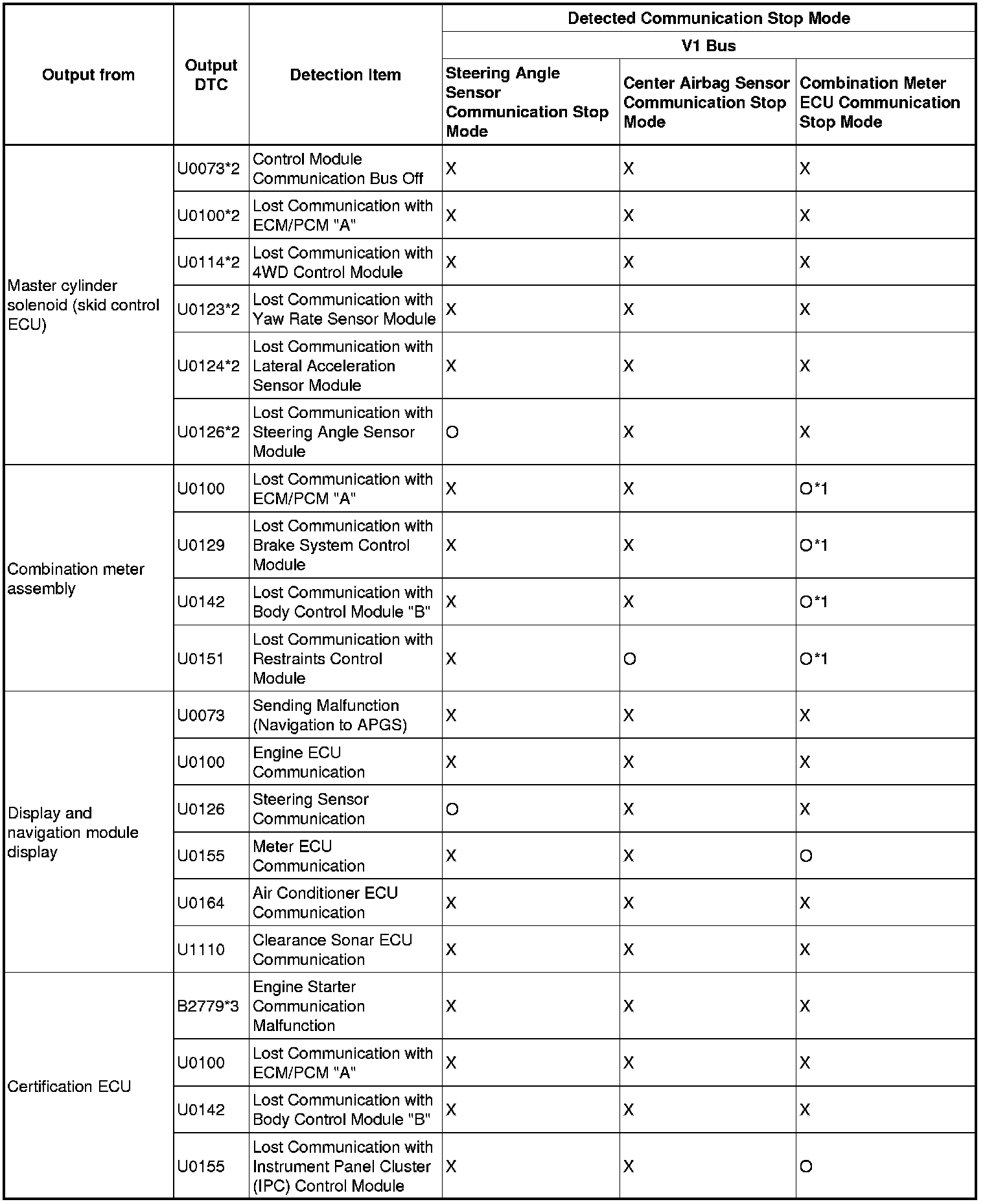
V1 Bus Vol. 3
V2 Bus Vol. 1
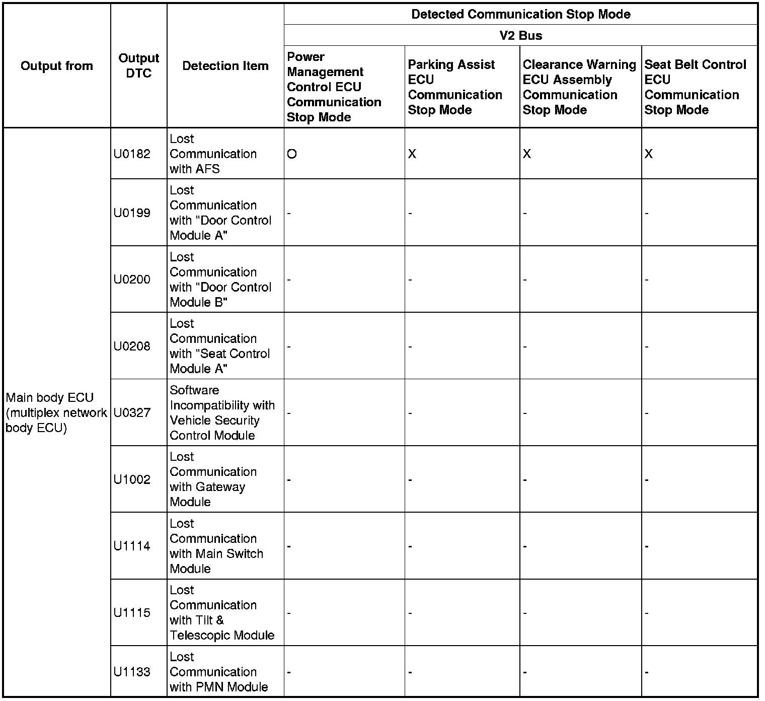
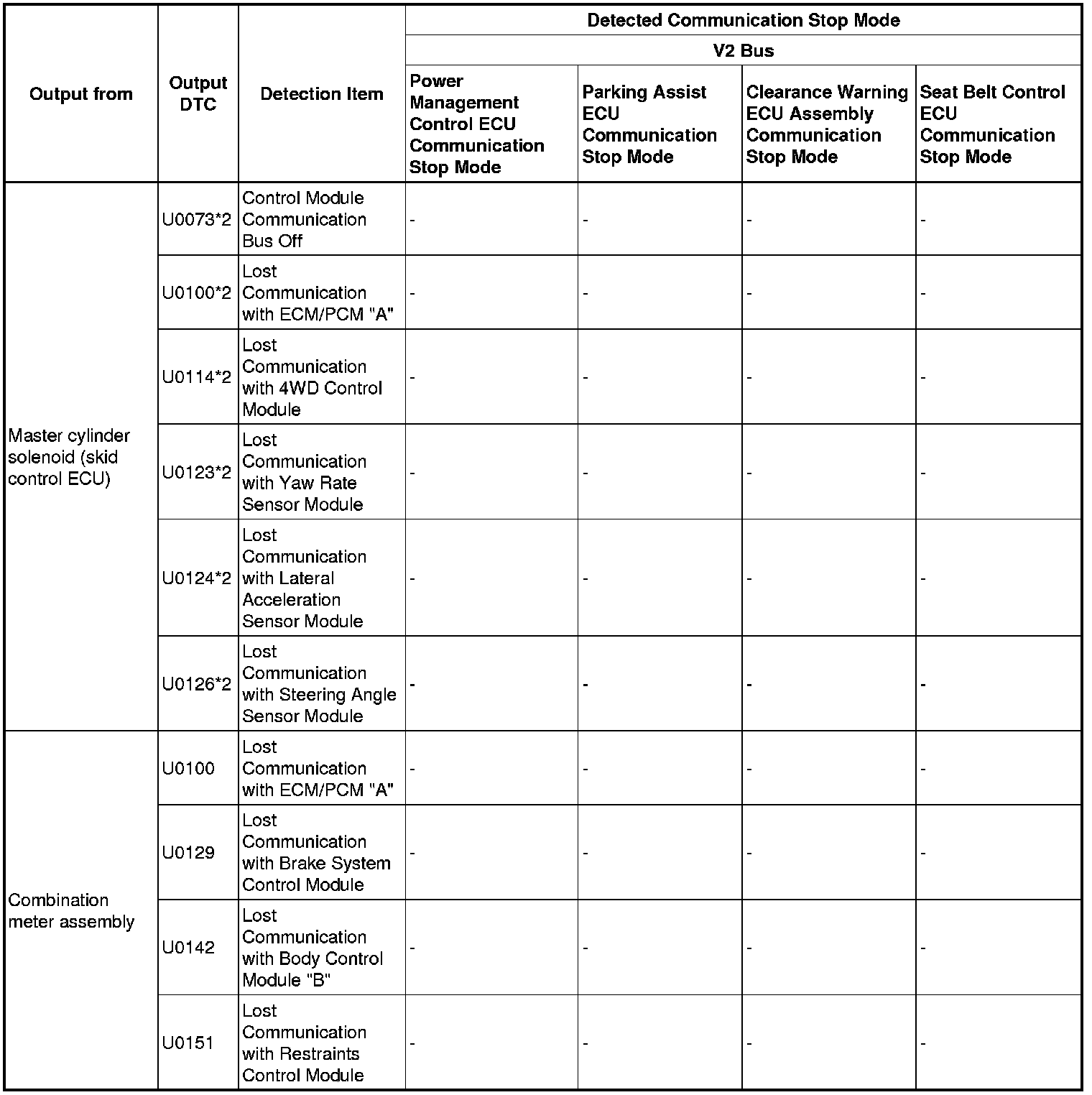
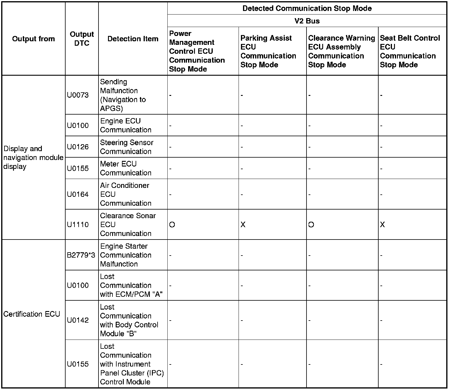
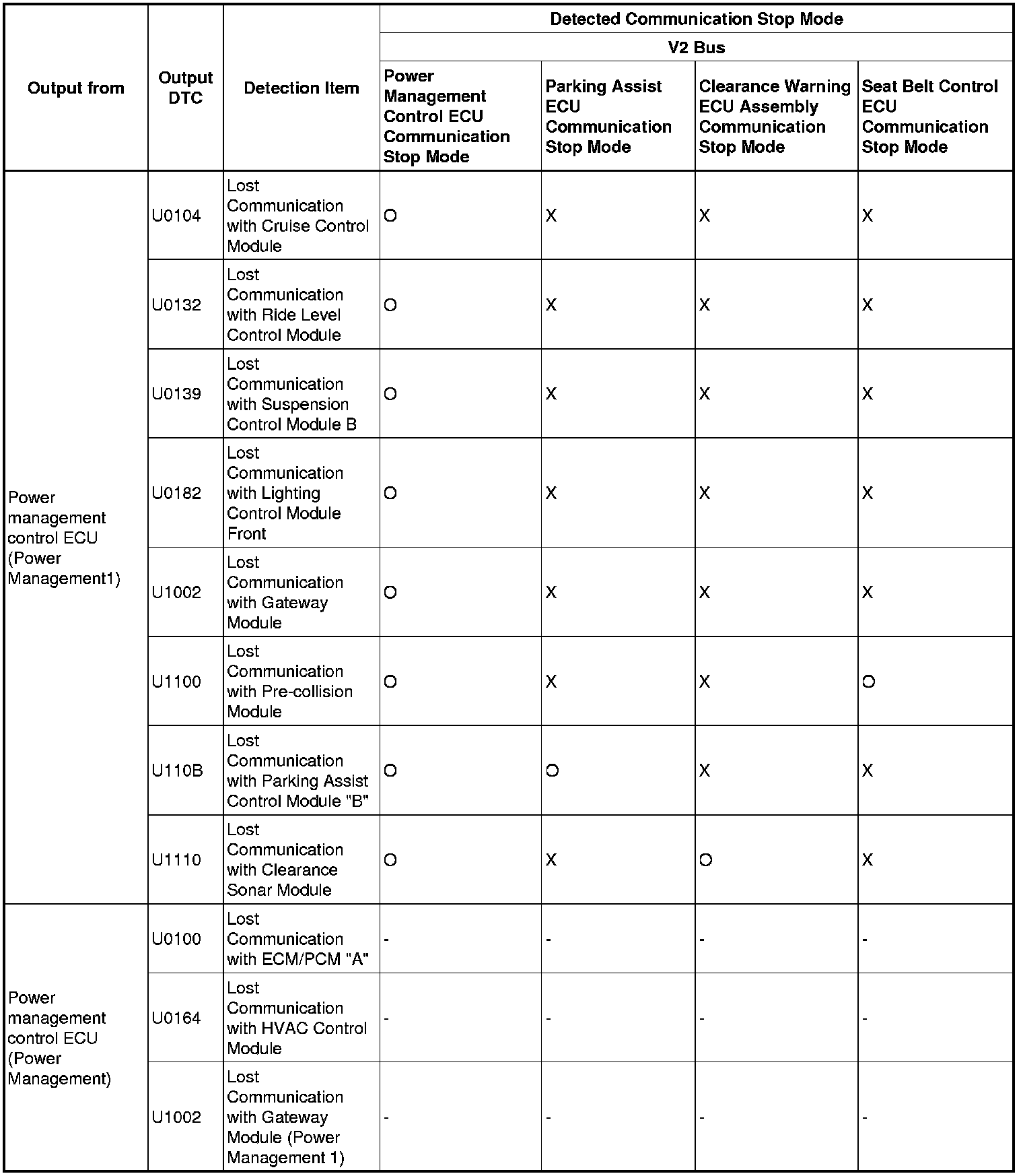
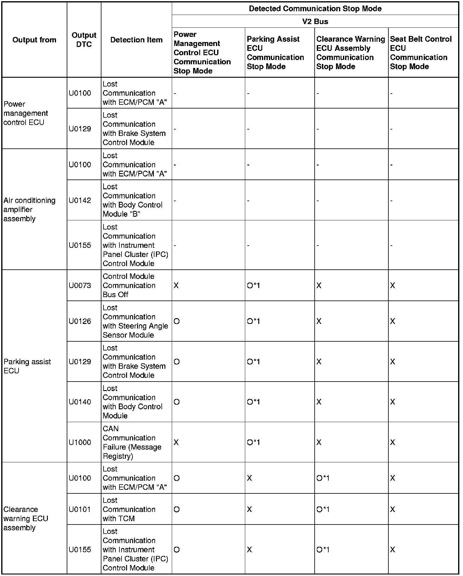
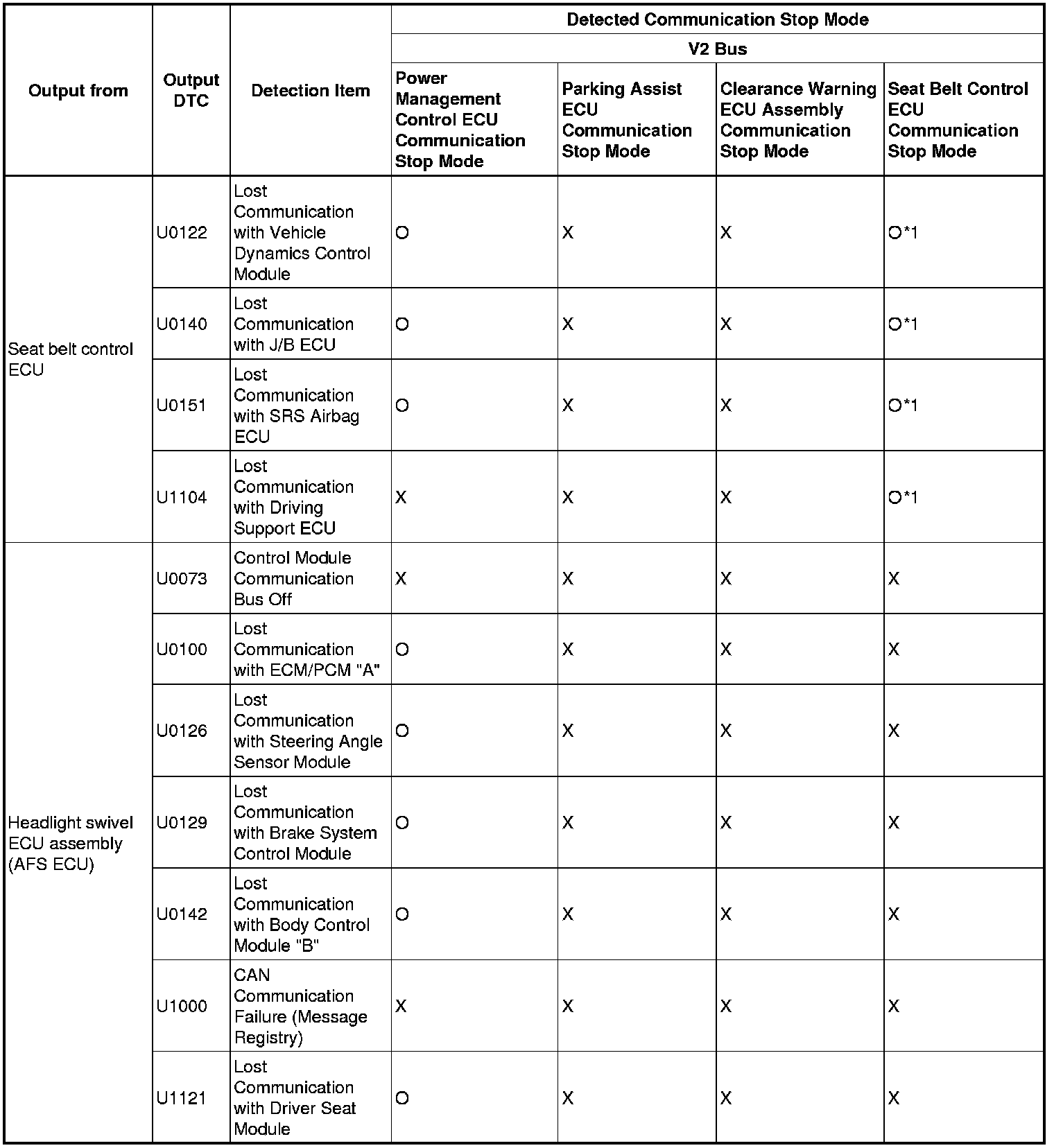
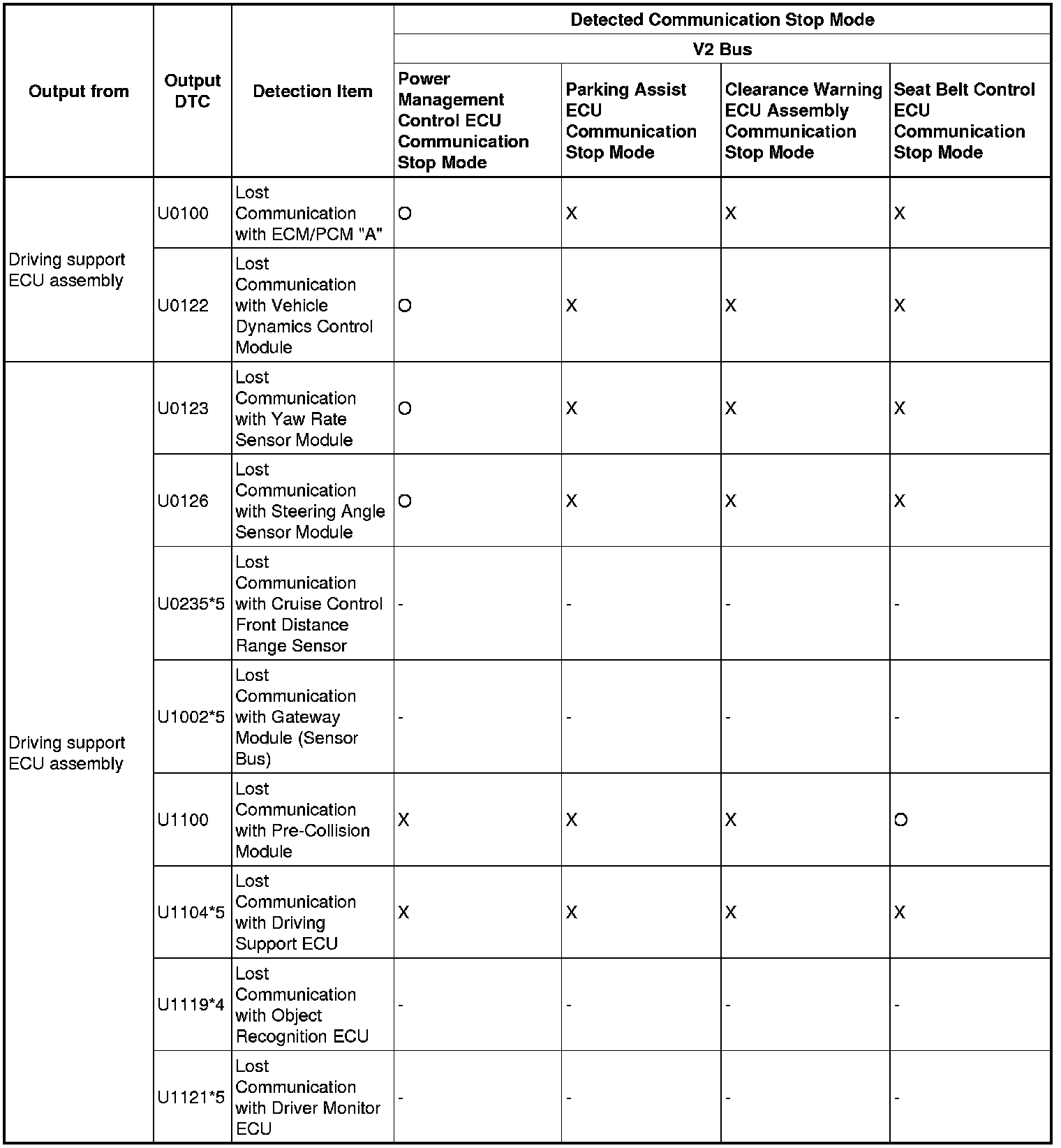
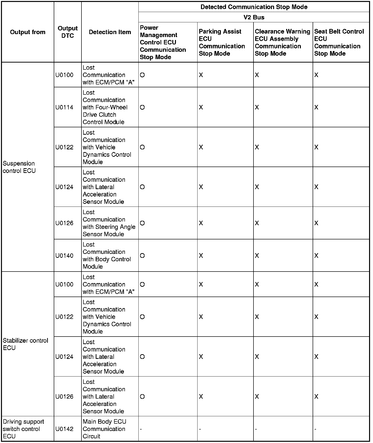
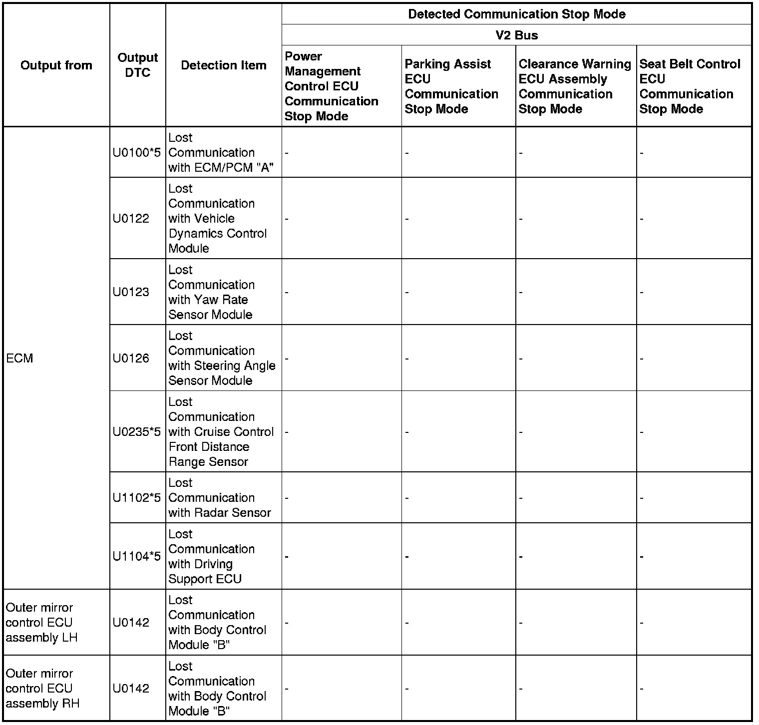
V2 Bus Vol. 2
Power Management Bus
MS Bus Vol. 1
MS Bus Vol. 2