Power Mirror Cannot Be Adjusted With Power Mirror Switch
MIRROR (EXT): POWER MIRROR CONTROL SYSTEM: Power Mirror cannot be Adjusted with Power Mirror Switch
- Power Mirror cannot be Adjusted with Power Mirror Switch
SYSTEM DESCRIPTION
The main body ECU (multiplex network body ECU) detects the mirror adjust switch status and sends the signal to the outer mirror control ECU assembly via CAN communication. Upon receiving the signal, each outer mirror control ECU assembly operates the vertical and horizontal mirror motors to adjust the mirror surface position.
WIRING DIAGRAM
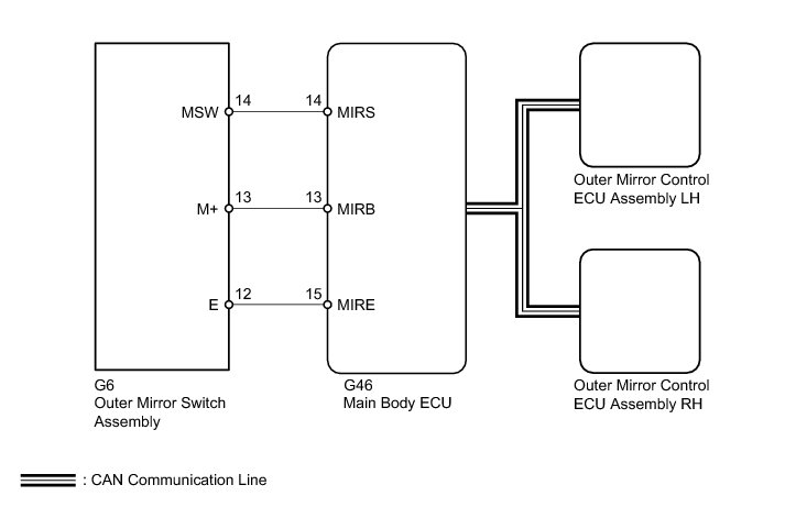
INSPECTION PROCEDURE
PROCEDURE
1. CHECK CAN COMMUNICATION SYSTEM
(a) Check if a CAN communication DTC is output Diagnosis System.
Result
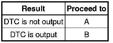
B -- GO TO CAN COMMUNICATION SYSTEM How to Proceed With Troubleshooting
A -- Continue to next step.
2. READ VALUE USING TECHSTREAM (OUTER MIRROR SWITCH)
(a) Using the Techstream, read the Data List Scan Tool Testing and Procedures.
Main Body
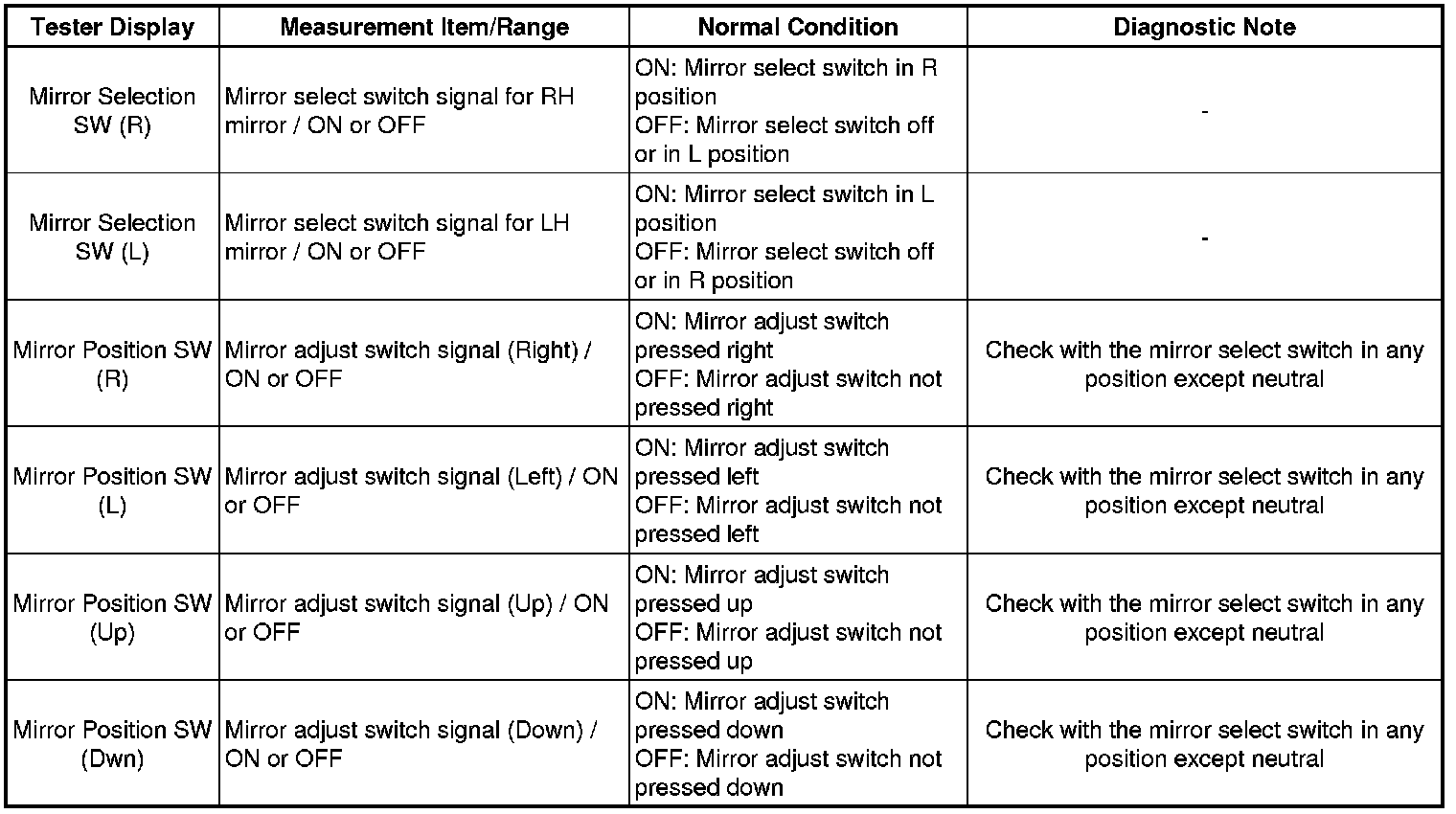
OK:
On the Techstream screen, each item changes between ON and OFF according to above chart.
NG -- INSPECT OUTER MIRROR SWITCH ASSEMBLY
OK -- REPLACE MAIN BODY ECU (MULTIPLEX NETWORK BODY ECU) Removal
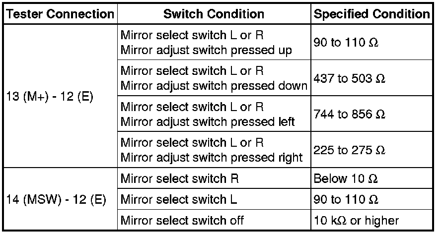
3. INSPECT OUTER MIRROR SWITCH ASSEMBLY
(a) Remove the outer mirror switch assembly Removal.
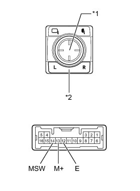
(b) Measure the resistance according to the value(s) in the table below.
Standard Resistance:
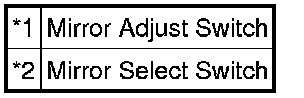
Text in Illustration
NG -- REPLACE OUTER MIRROR SWITCH ASSEMBLY Removal
OK -- Continue to next step.
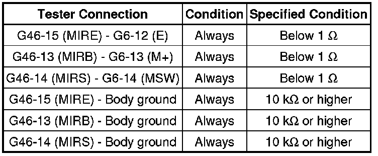
4. CHECK HARNESS AND CONNECTOR (MAIN BODY ECU - OUTER MIRROR SWITCH)
(a) Disconnect the G46 ECU connector.
(b) Disconnect the G6 switch connector.
(c) Measure the resistance according to the value(s) in the table below.
Standard Resistance:
NG -- REPAIR OR REPLACE HARNESS OR CONNECTOR
OK -- REPLACE MAIN BODY ECU (MULTIPLEX NETWORK BODY ECU) Removal