Unlock Position Sensor Signal Circuit
STEERING COLUMN: STEERING LOCK SYSTEM: Unlock Position Sensor Signal Circuit
- Unlock Position Sensor Signal Circuit
DESCRIPTION
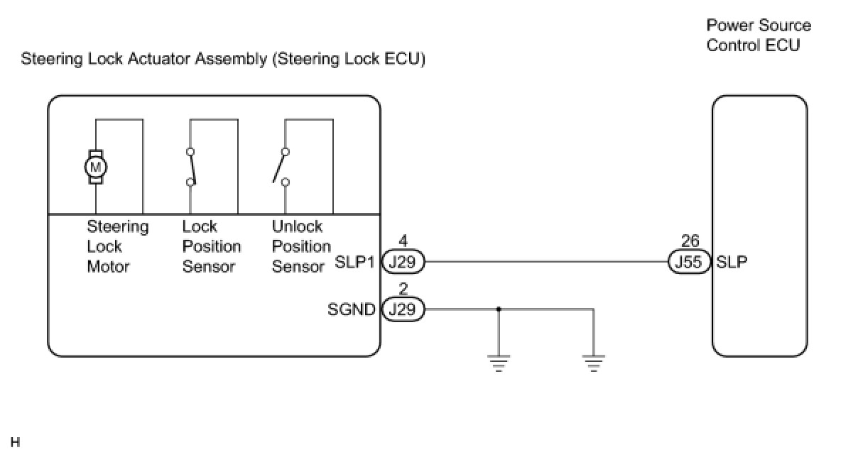
The unlock position sensor is one of the components comprising the steering lock actuator. The sensor switch contact closes when the steering lock is released. The steering lock release signal is then sent to the power source control ECU. Receiving the signal, the ECU permits engine start. (This prevents the engine from being started with the steering locked.)
WIRING DIAGRAM
INSPECTION PROCEDURE
PROCEDURE
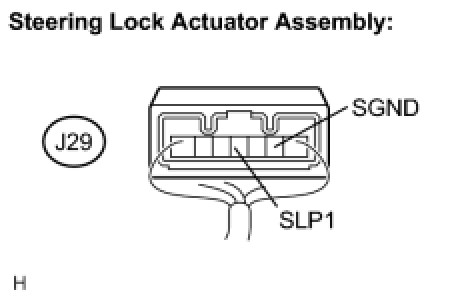
1. INSPECT STEERING LOCK ACTUATOR ASSEMBLY (STEERING LOCK ECU)
(a) Measure the voltage according to the value(s) in the table below.
Standard voltage:
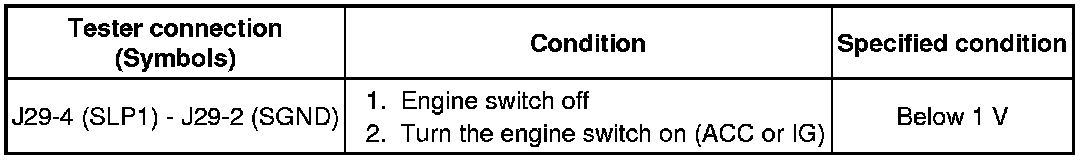
OK -- CHECK PUSH BUTTON START FUNCTION
NG -- Continue to next step.
2. CHECK HARNESS AND CONNECTOR (STEERING LOCK ACTUATOR ASSEMBLY - POWER SOURCE CONTROL ECU)
(a) Disconnect the J29 connector from the steering lock actuator assembly.
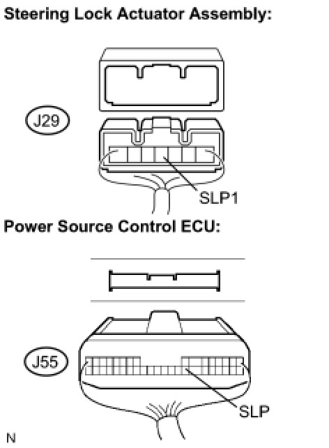
(b) Disconnect the J55 connector from the power source control ECU.
(c) Measure the resistance according to the value(s) in the table below.
Standard resistance:
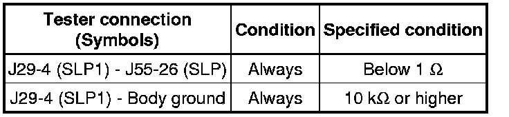
NG -- REPAIR OR REPLACE HARNESS OR CONNECTOR
OK -- REPLACE STEERING LOCK ACTUATOR ASSEMBLY