DVD Image Signal Circuit Between Radio Receiver and Navigation ECU
NAVIGATION / MULTI INFO DISPLAY: NAVIGATION SYSTEM (for DVD): DVD Image Signal Circuit between Radio Receiver and Navigation ECU
- DVD Image Signal Circuit between Radio Receiver and Navigation ECU
DESCRIPTION
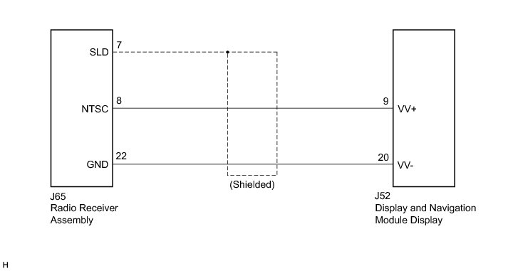
This circuit sends a DVD image signal from the radio receiver assembly to the display and navigation module display.
WIRING DIAGRAM
INSPECTION PROCEDURE
PROCEDURE
1. CHECK HARNESS AND CONNECTOR
(a) Disconnect the radio receiver assembly connector.
(b) Disconnect the display and navigation module display connector.
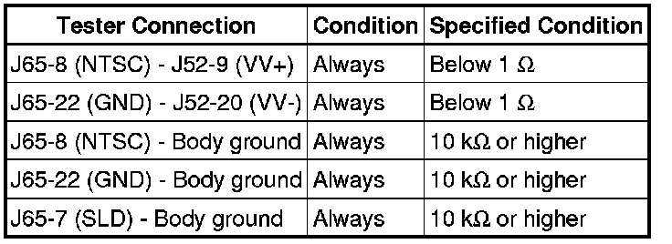
(c) Measure the resistance according to the value(s) in the table below.
Standard Resistance:
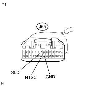
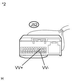
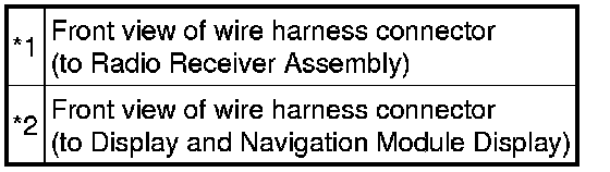
Text in Illustration
NG -- REPAIR OR REPLACE HARNESS OR CONNECTOR
OK -- Continue to next step.
2. INSPECT RADIO RECEIVER ASSEMBLY
(a) Reconnect the radio receiver assembly connector.
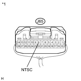
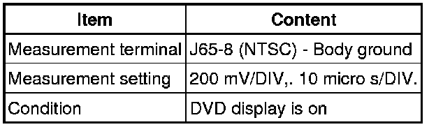
(b) Measure the waveform according to the table below.

Oscilloscope Waveform
NOTICE:
The video waveform changes according to the image output from the radio receiver assembly to the display and navigation module display, but the synchronization signal does not change.
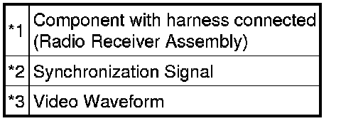
Text in Illustration
NG -- REPLACE RADIO RECEIVER ASSEMBLY Removal
OK -- PROCEED TO NEXT SUSPECTED AREA SHOWN IN PROBLEM SYMPTOMS TABLE Problem Symptoms Table