Power Source Circuit
STEERING COLUMN: STEERING LOCK SYSTEM: Power Source Circuit
- Power Source Circuit
DESCRIPTION
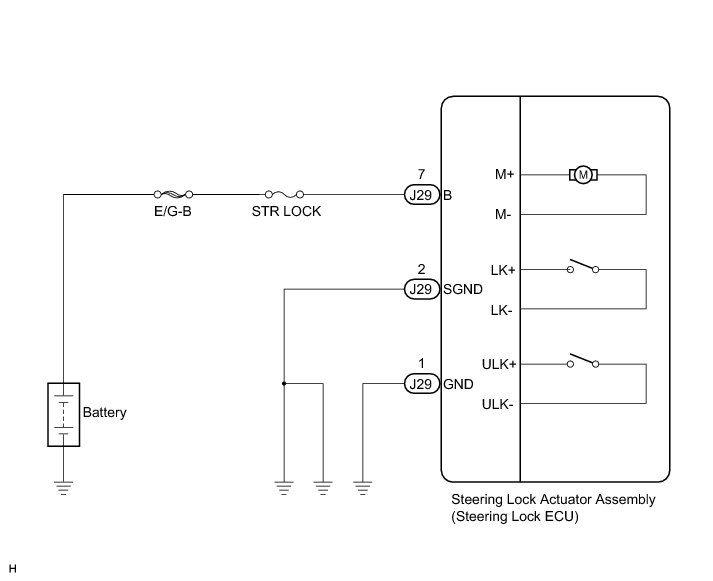
This circuit supplies power source voltage from the battery to terminal B of the steering lock ECU. This is used as power source for the CPU, motor, communication, and peripheral circuits.
WIRING DIAGRAM
INSPECTION PROCEDURE
PROCEDURE
1. CHECK HARNESS AND CONNECTOR (STEERING LOCK ACTUATOR ASSEMBLY - BODY GROUND)
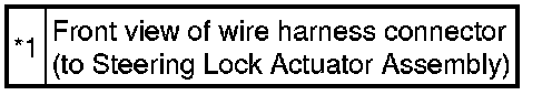
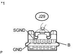
(a) Disconnect the J29 connector from the steering lock actuator assembly.
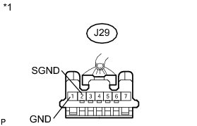
Text in Illustration
(b) Measure the resistance according to the value(s) in the table below.
Standard Resistance:
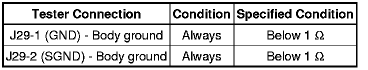
NG -- REPAIR OR REPLACE HARNESS OR CONNECTOR
OK -- Continue to next step.
2. CHECK HARNESS AND CONNECTOR (STEERING LOCK ACTUATOR ASSEMBLY - BATTERY)
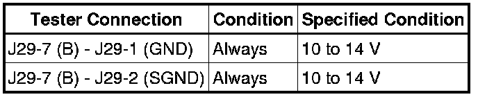
(a) Measure the voltage according to the value(s) in the table below.
Standard Voltage:
Text in Illustration

NG -- REPAIR OR REPLACE HARNESS OR CONNECTOR (STEERING LOCK ACTUATOR ASSEMBLY - BATTERY)
OK -- PROCEED TO NEXT SUSPECTED AREA SHOWN IN PROBLEM SYMPTOMS TABLE Steering Lock System