Disassembly and Assembly
Transfer CasePart 1 Of 2:
Part 2 Of 2:
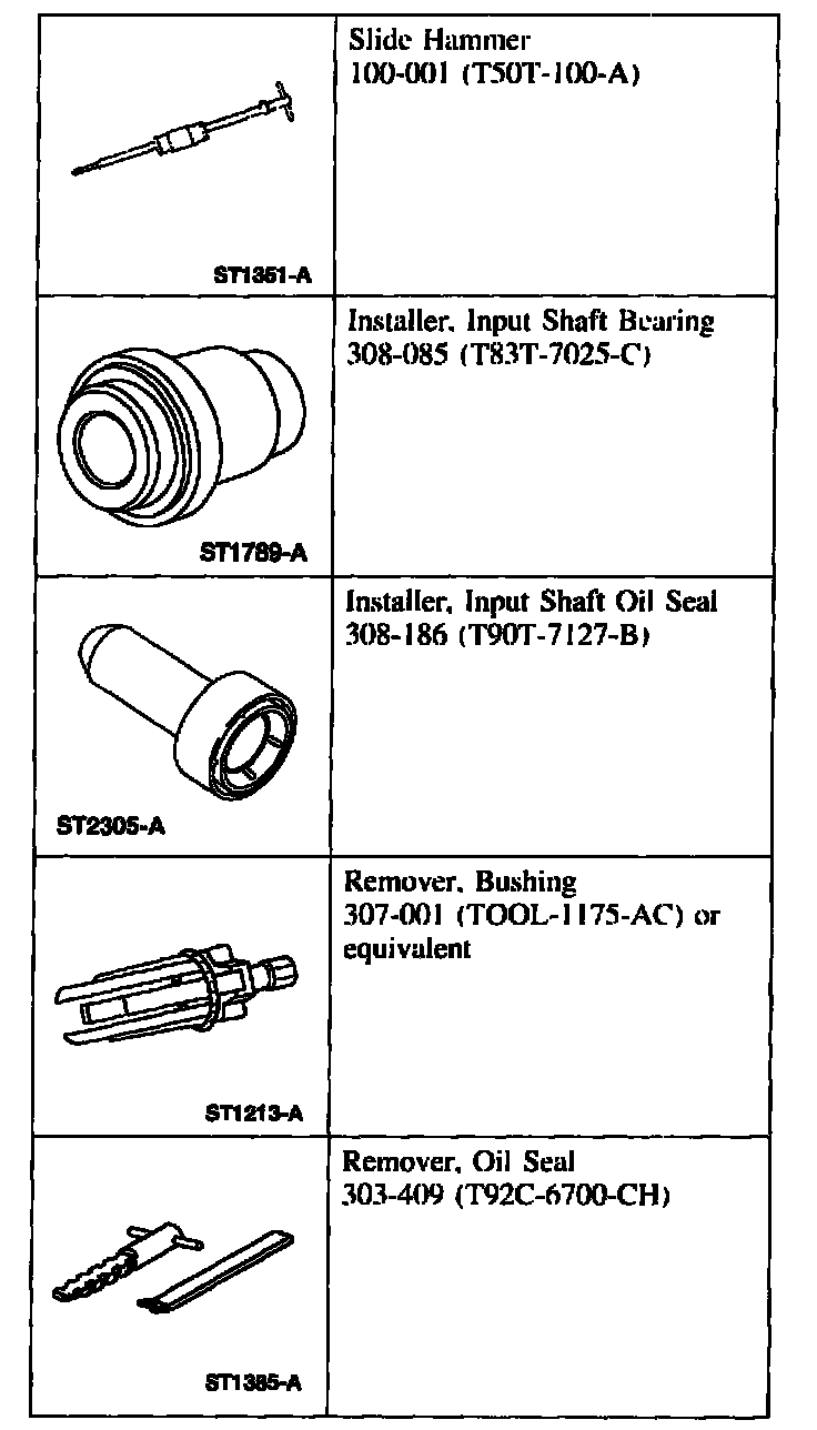
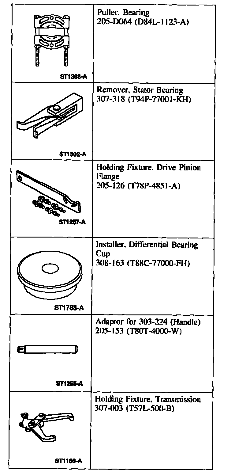
Special Tool(s)
Disassembly and Assembly
1. CAUTION: Discard all seals after removing them.
Remove the transfer case from the vehicle.
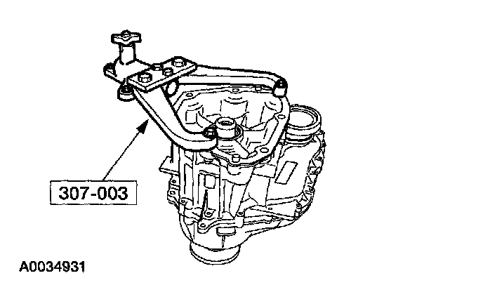
2. WARNING: Make sure the holding fixture lock pin is secure.
Using the special tool, secure the transfer case to a bench.
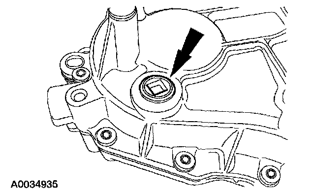
3. Remove the dampener.
4. Remove the drain plug and drain the fluid, if not done previously.
^ Install the drain plug when finished draining.
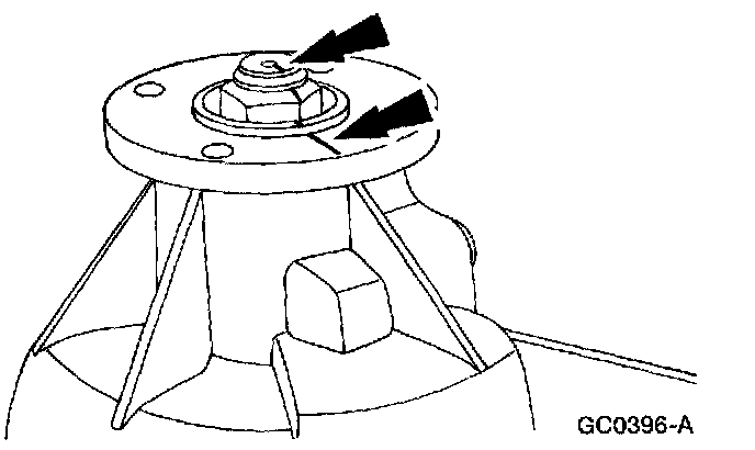
5. Index-mark the rear output flange and the upper output shaft.
Part 1 Of 5:
Part 2 Of 5:
Part 3 Of 5:
Part 4 Of 5:
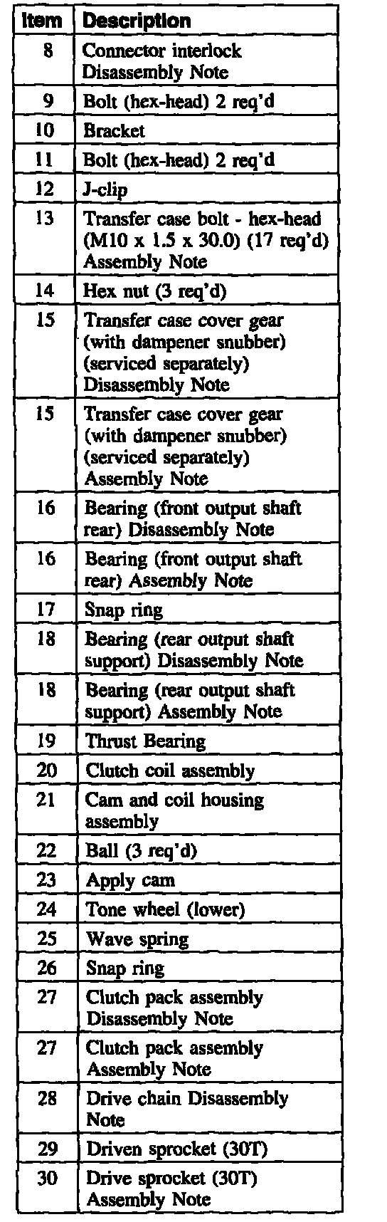
Part 5 Of 5:
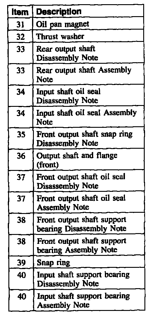
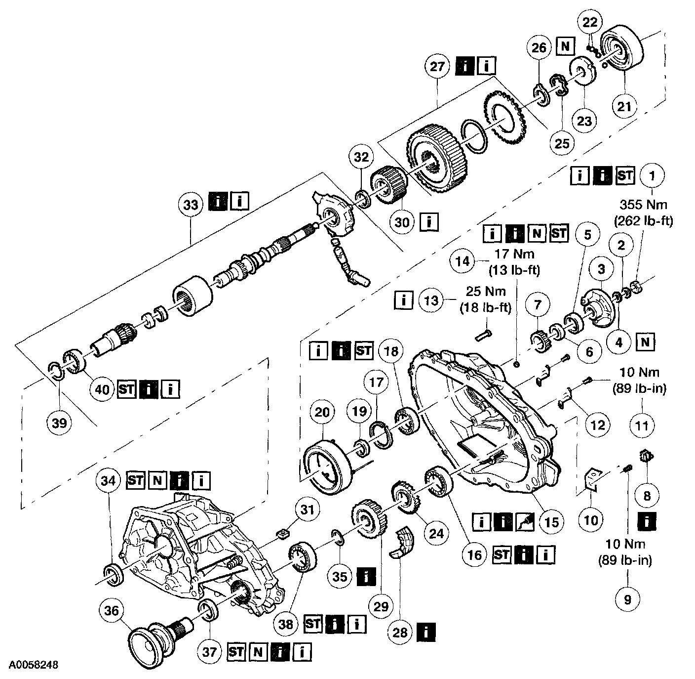
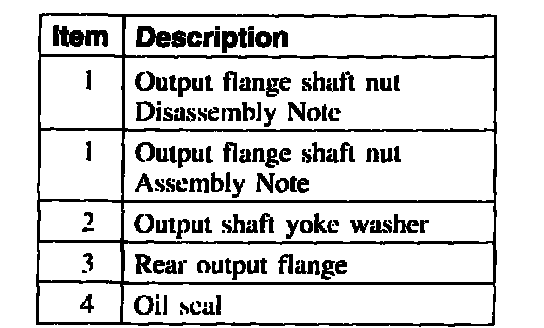
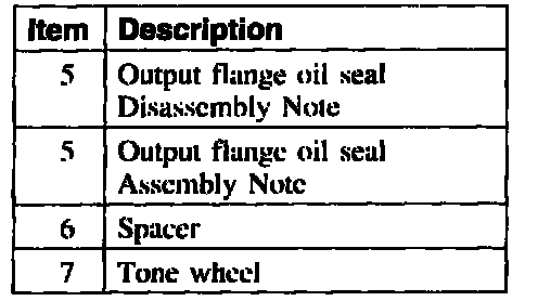
6. Remove the components in the order indicated in the following illustration and table.
7. To assemble, reverse the disassembly procedure.
Item 1: Output Flange Nut Disassembly Note
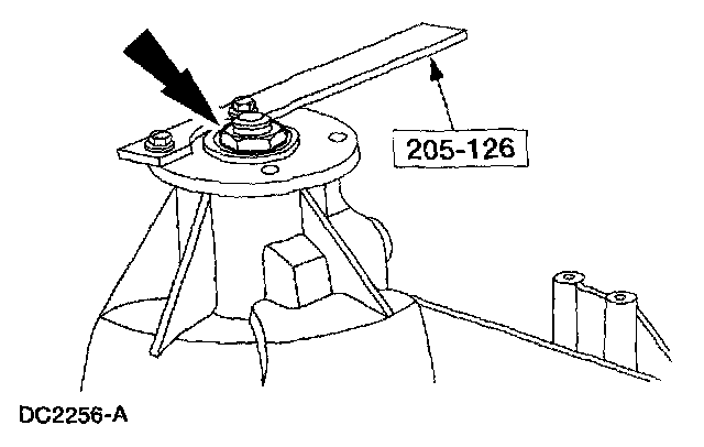
1. Using the special tool to hold the output flange. remove the nut.
Item 5: Output Flange Oil Seal Disassembly Note
1. Using the special tools. remove the oil seal.
Item 8: Connector Interlock Disassembly Note
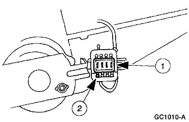
1. Remove the coil wire pin from the electrical connector.
1 Remove the connector interlock.
2 Remove the coil wire pin,
3 Use electrical connector pin extractor tool.
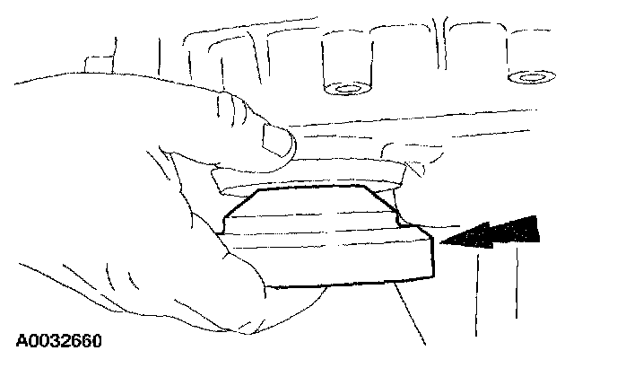
Item 15: Transfer Case Cover Gear Disassembly Note
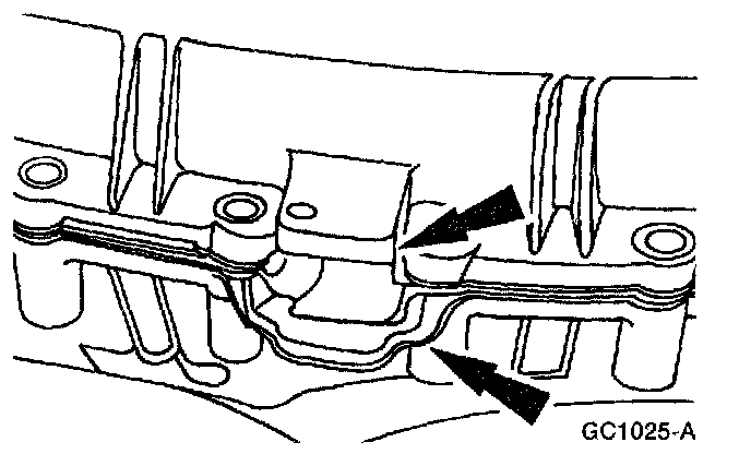
1. Separate the transfer case halves at the transfer case pry bosses.
Item 16: Front Output Shaft Rear Bearing Disassembly Note
1. Using the special tool, remove the bearing.
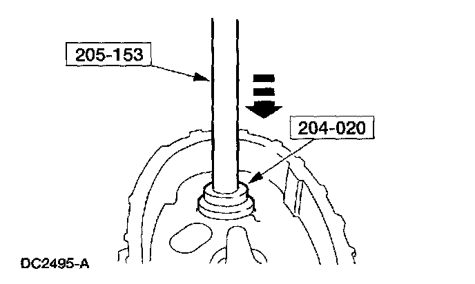
Item 18: Rear Output Shaft Support Bearing Disassembly Note
1. Using the special tool, remove the bearing.
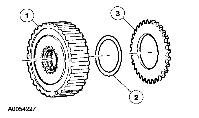
Item 27: Clutch Pack Disassembly Note
Part 1 Of 2:
Part 2 Of 2:
1. CAUTION: When removing or installing the clutch pack assembly, do not separate the clutch pack assembly. Keep tension on the clutch pack upon removal. Set the clutch pack assembly on the bench in the same position as it was located in the transfer case. The thrust washer in the lower clutch pack uses tabs to hold it in place. If the thrust washer is not in place, a transfer case clearance problem can occur.
Remove the clutch pack.
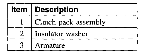
Item 28: Drive Chain Disassembly Note
1. Remove the drive chain, driven sprocket and drive sprocket as an assembly.
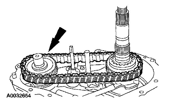
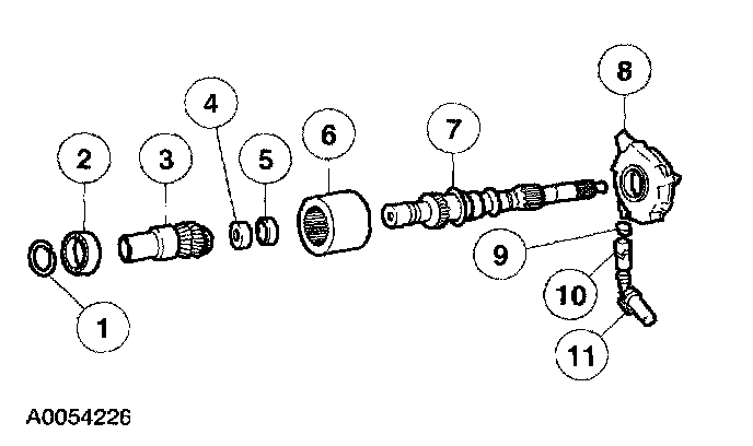
Item 33: Rear Output Shaft Assembly Disassembly Note
Part 1 Of 2:
Part 2 Of 2:
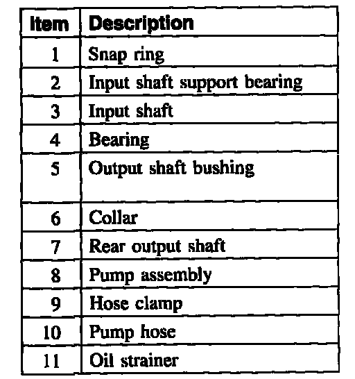
1. CAUTION: Do not disassemble the pump assembly.
Remove the rear output shaft, pump assembly, and input shaft as an assembly.
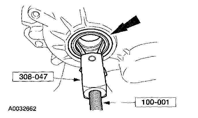
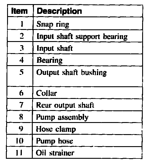
Item 34: Input Shaft Oil Seal Disassembly Note
1. Using the special tool, remove the oil seal.
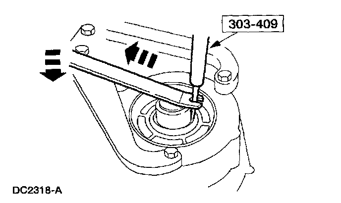
Item 35: Front Output Shaft Snap Ring Disassembly Note
1. Holding the front output shaft, remove the snap ring.
Item 37: Front Output Shaft Oil Seal Disassembly Note
1. Using the special tools, remove the oil seal.
Item 38: Front Output Shaft Support Bearing Disassembly Note
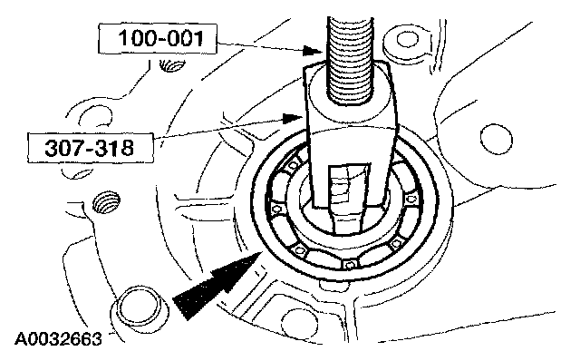
1. Using the special tools, remove the bearing.
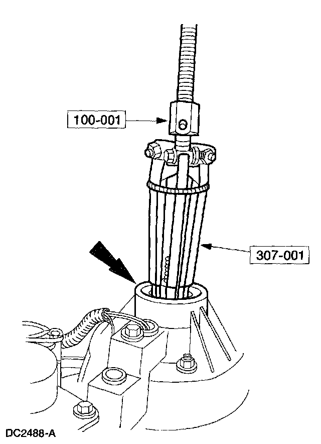
Item 40: Input Shaft Support Bearing Disassembly Note
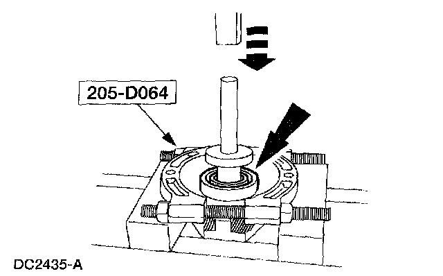
1. Using a suitable press and the special tool, remove the bearing.
Item 1: Output Flange Nut Assembly Note
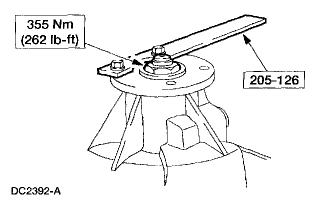
1. Using the special tool to hold the rear output flange, install the nut.
Item 5: Output Flange Oil Seal Assembly Note
1. Using the special tool, install the seal.
Item 13: Transfer Case Bolt Assembly Note
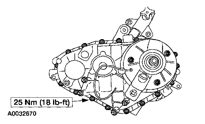
1. Install the bolts. Tighten them evenly in a star pattern.
Item 15: Transfer Case Cover Assembly Note
1. CAUTION: Applying too much silicone sealant can plug the fluid filter and cause transfer case failure.
NOTE: Make sure the transfer case mating surfaces are clean,
Apply a 3 mm (1/8 inch) bead of sealant to the transfer case mating surfaces.
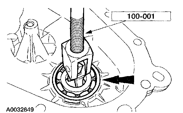
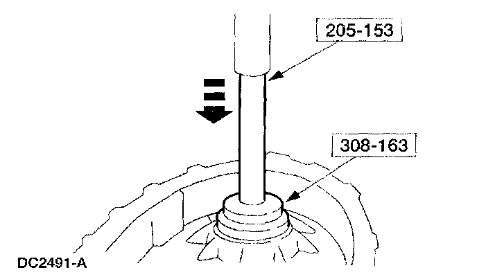
Item 16: Front Output Shaft Rear Bearing Assembly Note
1. Using the special tools, press the bearing into the case.
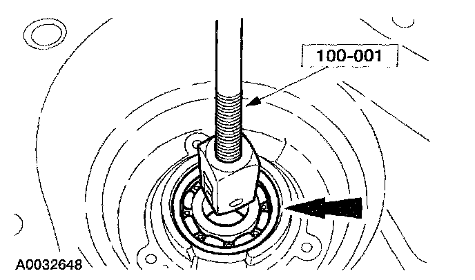
Item 18: Rear Output Shaft Support Bearing Assembly Note

1. Using the special tools, press the bearing into the case.
Item 27: Clutch Pack Assembly Note
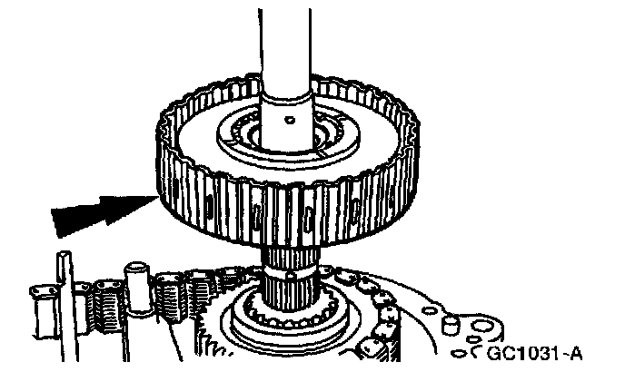
1. CAUTION: When removing or installing the clutch pack assembly, do not separate the clutch pack assembly. Keep tension on the clutch pack upon removal. Set the clutch pack assembly on the bench in the same position as it was located in the transfer case. The thrust washer in the lower clutch pack uses tabs to hold it in place. If the thrust washer is not in place, a transfer case clearance problem can occur.
Install the clutch pack assembly.
Item 30: Drive Sprocket Assembly Note
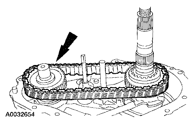
1. Install the drive chain, driven sprocket and the drive sprocket as an assembly.
Item 33: Rear Output Shaft Assembly Assembly Note
Part 1 Of 2:
Part 2 Of 2:
1. CAUTION: Do not disassemble the pump assembly.
Install the rear output shaft, pump assembly, and input shaft as an assembly.
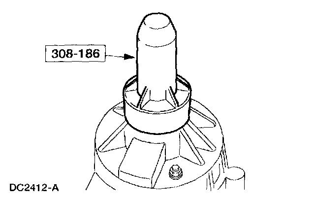
Item 34: Input Shaft Oil Seal Assembly Note
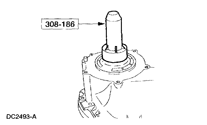
1. Using the special too], install the oil seal.
Item 37: Front Output Shaft Oil Seal Assembly Note
1. Using the special tool, install the oil seal.
Item 38: Front Output Shaft Support Bearing Assembly Note
1. Using the special tools, press the bearing into the case.
Item 40: Input Shaft Support Bearing Assembly Note
1. Using a suitable press, install the bearing onto the input shaft.