Air Conditioning
AIR CONDITIONINGThe air conditioning system components are:
- A/C compressor.
- A/C condenser core.
- A/C evaporator core.
- receiver/drier.
- connecting refrigerant lines.
- thermostatic expansion valve.
- evaporator discharge air temperature sensor.
- A/C high-pressure cutoff switch.
- low charge protection switch.
- A/C compressor pressure relief valve.
The refrigerant system incorporates an A/C compressor controlled by the powertrain control module (PCM) through an A/C clutch relay.
The A/C compressor clutch will only be engaged by the PCM if all of the following conditions are met:
- The climate control assembly is set to a mode which provides an A/C request to the PCM.
- The evaporator discharge air temperature sensor is reading a temperature above 37°F.
- The high-pressure cutoff switch is not open due to excessive pressure in the high side of the refrigerant system.
- The low charge protection switch is not open due to insufficient low side refrigerant system pressure.
- The A/C compressor relay is switched to the CLOSED position by the PCM.
- The engine coolant temperature is not excessively high.
- The PCM has not detected a wide open throttle (WOT) condition.
An A/C compressor pressure relief valve is installed in the compressor manifold and tube assembly to protect the refrigerant system against excessively high refrigerant pressures.
Refrigerant flow into the evaporator core is metered by a thermostatic expansion valve.
A/C Compressor and Clutch Assembly
NOTE:
- Internal A/C compressor components are not serviced separately. The SC115 A/C compressor is serviced only as an assembly. The clutch plate, clutch pulley and bearing, and clutch field coil are serviceable.
- Installation of a new receiver/drier is not required when repairing the air conditioning system except when there is physical evidence of system contamination from a failed A/C compressor or damage to the receiver/drier.
The SC115 A/C compressor has the following characteristics:
- Tangential mount design - 3 lugs.
- The single manifold block of the compressor manifold and tube assembly fits to the suction and discharge ports. Two O-ring seals are used for sealing.
- An eccentric bushing is driven by the shaft of the A/C compressor.
- An orbiting scroll driven by the eccentric bushing compresses the refrigerant gas against the walls of the fixed scroll.
- Single reed-type discharge valve mounted on the back of the fixed scroll. There are no suction valves.
- Non-serviceable shaft seal fully supported on both sides by bearings.
- The A/C compressor uses PAG oil or equivalent. This oil contains special additives required for the A/C compressor.
- The A/C compressor oil from vehicles equipped with an SC115 A/C compressor may have some slightly dark-colored streaks while maintaining normal oil viscosity. This is normal for this A/C compressor because of break-in wear of the scroll seals that can discolor the oil.
- Use standard oil matching procedures when installing new compressors.
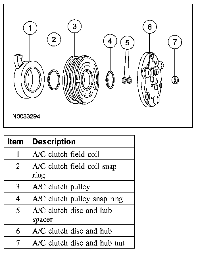
When battery voltage is applied to the A/C compressor clutch field coil, the clutch plate and hub assembly is drawn toward the A/C clutch pulley. The magnetic force locks the clutch plate and hub assembly and the A/C clutch pulley together as one unit, causing the compressor shaft to rotate. When battery voltage is removed from the A/C compressor clutch field coil, springs in the clutch plate and hub assembly move the clutch plate away from the A/C clutch pulley.
Thermostatic Expansion Valve
The thermostatic expansion valve (TXV) is located between the evaporator core lines and the thermostatic expansion valve manifold and tube assembly at the RH rear of the engine compartment. The TXV provides a restriction to the flow of refrigerant from the high-pressure side of the refrigerant system, and separates the low-pressure and high-pressure sides of the refrigerant system. Refrigerant entering and exiting the evaporator core passes through the TXV through 2 separate flow paths. An internal temperature sensing bulb senses the temperature of the refrigerant flowing out of the evaporator core and adjusts an internal pin-type valve to meter the refrigerant flow into the evaporator core. The internal pin-type valve decreases the amount of refrigerant entering the evaporator core at lower temperatures, and increases the amount of refrigerant entering the evaporator core at higher temperatures.
Evaporator Discharge Air Temperature Sensor
The evaporator discharge air temperature sensor monitors the temperature of the air exiting the evaporator core. It is used (by the PCM) to prevent freezing of the evaporator core by controlling A/C compressor clutch engagement/disengagement. Battery voltage is sent to the evaporator discharge air temperature sensor when the ignition switch is in the RUN position. The evaporator discharge air temperature sensor either completes the circuit to the PCM (when the temperature rises) or interrupts the circuit (when the temperature drops). The PCM engages the A/C compressor clutch when the circuit is complete and an A/C request has been received from the climate control assembly. For specifications regarding operating temperature(s), refer to Specifications.
Low Charge Protection Switch
The low charge protection switch is used to prevent A/C compressor damage in the event of a low refrigerant charge, by interrupting the evaporator discharge air temperature sensor signal to the PCM, when the low side refrigerant pressure drops below acceptable levels. The electrical switch contacts open when the suction pressure drops below normal levels. The contacts close when the suction pressure rises. For specifications regarding operating pressure(s), refer to Specifications.
High-Pressure Cutoff Switch
The high-pressure cutoff switch is used to interrupt A/C compressor operation, by interrupting the evaporator discharge air temperature sensor signal to the PCM, in the event of high system discharge pressures. When the A/C compressor discharge pressure rises, the switch contacts open to disengage the A/C compressor. When the pressure drops, the contacts close to allow operation of the A/C compressor. For specifications regarding operating pressure(s), refer to Specifications.
The high-pressure cutoff switch is mounted on a Schrader valve-type fitting on the high-pressure side of the compressor manifold and tube assembly. It is not necessary to discharge the refrigerant system to remove the high-pressure cutoff switch.
Condenser Core
NOTE: Installation of a new receiver/drier is not required when repairing the air conditioning system except when there is physical evidence of system contamination from a failed A/C compressor or damage to the receiver/drier.
The condenser is an aluminum fin and tube design heat exchanger, located in front of the vehicle radiator. It cools compressed refrigerant gas by allowing air to pass over fins and tubes to extract heat, and by condensing gas to liquid refrigerant as it is cooled.
Evaporator Core
NOTE:
- If an evaporator core leak is suspected, the evaporator core must be vacuum leak tested before it is removed from the vehicle.
- Installation of a new receiver/drier is not required when repairing the air conditioning system except when there is physical evidence of system contamination from a failed A/C compressor or damage to the receiver/drier.
The evaporator core is an aluminum plate/fin type and is located in the heater core and evaporator core housing. A mixture of refrigerant and oil enters the bottom of the evaporator core through the evaporator core inlet tube, continues over to the remaining plate/fin sections, and then moves out of the evaporator core through the evaporator core outlet tube. Air from the blower motor is cooled and dehumidified as it flows through the evaporator core fins.
Receiver/Drier
NOTE: Installation of a new receiver/drier is not required when repairing the refrigerant system except when there is physical evidence of contamination from a failed A/C compressor or damage to the receiver/drier.
The receiver/drier is mounted to the right of the radiator support. It stores high-pressure liquid after it leaves the condenser core. A desiccant bag mounted inside the receiver/drier removes any retained moisture from the refrigerant.
A/C Compressor Pressure Relief Valve
An A/C compressor pressure relief valve is incorporated in the compressor manifold and tube assembly to prevent damage to the A/C compressor and other system components, and to avoid total refrigerant loss by relieving unusually high refrigerant system discharge pressure buildups.
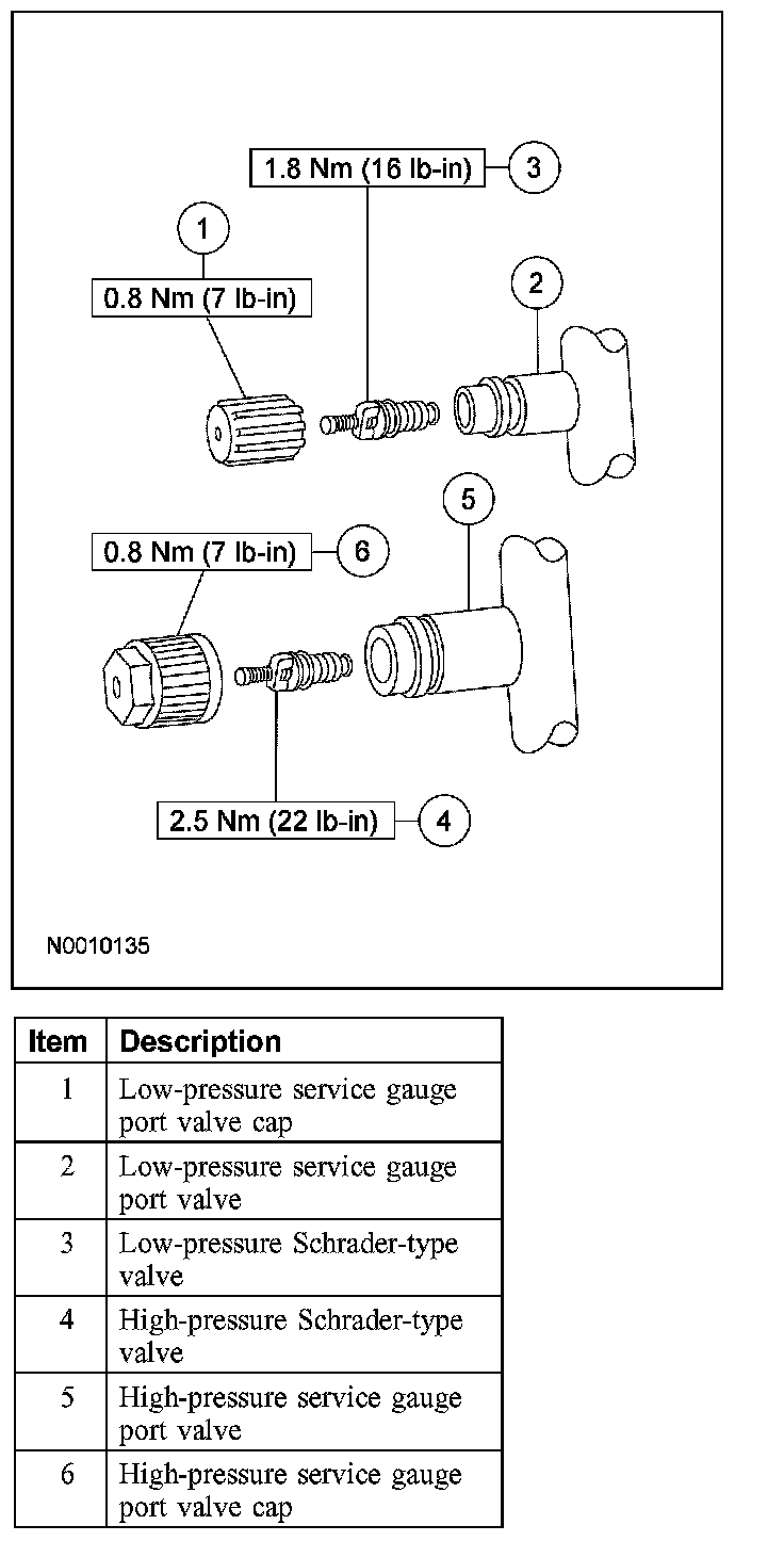
Service Gauge Port Valves
The high-pressure service gauge port valve is located on the compressor manifold and tube assembly near the condenser fitting.
The low-pressure service gauge port valve is located on the evaporator-to-suction accumulator line near the evaporator fitting.
The fitting is an integral part of the refrigeration line or component.
- Special couplings are required for both the high-side and low-side service gauge ports.
- A very small amount of leakage will always be detectable around the Schrader-type valve with the service gauge port valve cap removed, and is considered normal. A new Schrader-type valve core can be installed if the seal leaks excessively.
- The service gauge port valve caps are used as primary seals in the refrigerant system to prevent leakage through the Schrader-type valves from reaching the atmosphere. Always install and tighten the A/C service gauge port valve caps to the correct torque after they are removed.