Trailing Arm: Service and Repair
Trailing Arm
Front Wheel Drive (FWD) Vehicles

All-Wheel Drive (AWD) Vehicles


Removal and Installation
NOTICE: Suspension fasteners are critical parts because they affect performance of vital components and systems and their failure may result in major service expense. New parts must be installed with the same part numbers or equivalent part, if replacement is necessary. Do not use a replacement part of lesser quality or substitute design. Torque values must be used as specified during reassembly to make sure of correct retention of these parts.
All-Wheel Drive (AWD) vehicles
1. Remove the wheel and tire. For additional information, refer to Wheels and Tires.
All vehicles
2. Remove the parking brake cable bracket bolt and position the parking brake cable aside.
- To install, tighten to 10 Nm (89 lb-in).

Front Wheel Drive (FWD) vehicles
3. Remove the wheel spindle. For additional information, refer to Wheel Spindle Service and Repair.
4. If equipped, detach the wheel speed sensor harness from the trailing arm.

5. Using a suitable jack, support the trailing arm.
6. WARNING: The coil spring is under extreme load. Care must be taken at all times when removing or installing a loaded spring. Failure to follow this instruction may result in serious personal injury.
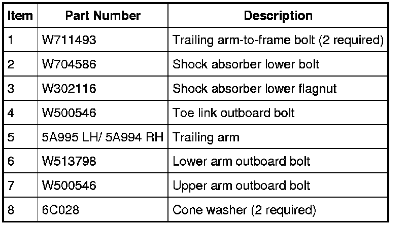
Remove and discard the lower arm outboard bolt.
- To install, tighten the new bolt to 103 Nm (76 lb-ft) with the suspension at the bushing fastener tightening position.
7. Remove and discard the upper arm outboard bolt.
- To install, tighten the new bolt to 110 Nm (81 lb-ft) with the suspension at the bushing fastener tightening position.
8. Carefully lower the trailing arm and remove the jack.
9. Remove and discard the shock absorber lower bolt and flagnut.
- To install, tighten the new bolt and flagnut to 115 Nm (85 lb-ft) with the suspension at the bushing fastener tightening position.
10. Remove and discard the toe link outboard bolt.
- To install, tighten the new bolt to 110 Nm (81 lb-ft) with the suspension at the bushing fastener tightening position.
AWD vehicles
11. Remove the wheel speed sensor harness bracket nut and position aside the bracket.
- To install, tighten to 23 Nm (17 lb-ft).
12. Remove the toe link. For additional information, refer to Toe Link Service and Repair.
13. Remove the 4 trailing arm-to-wheel knuckle nuts and the trailing arm toe link bracket.
- Discard the nuts.
- To install, tighten the new nuts to 100 Nm (74 lb-ft).
All vehicles
14. Remove the 2 trailing arm-to-frame bolts, cone washers and the trailing arm.
- Discard the bolts.
- To install, tighten the new bolts to 125 Nm (92 lb-ft).
15. NOTICE: Before tightening any suspension bushing fasteners, the suspension must be at the bushing fastener tightening position. Use a suitable jack to raise the suspension until the distance between the center of the hub and the lip of the fender is equal to 395 mm (15.55 in). This will prevent incorrect clamp load and bushing damage.
To install, reverse the removal procedure.

16. Check and, if necessary, align the rear end. For additional information, refer to Suspension &/or Alignment.