Steps 91-135
Engine
Engine Upper
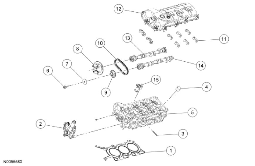
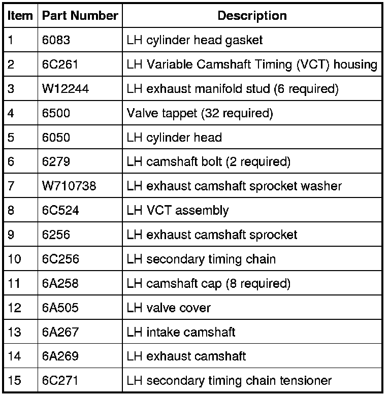
Engine Upper - LH Cylinder Head
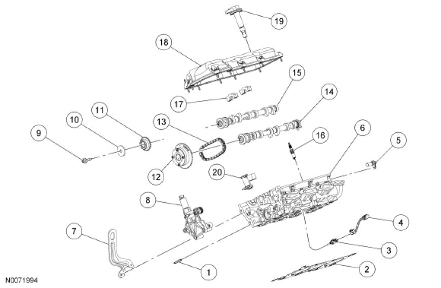
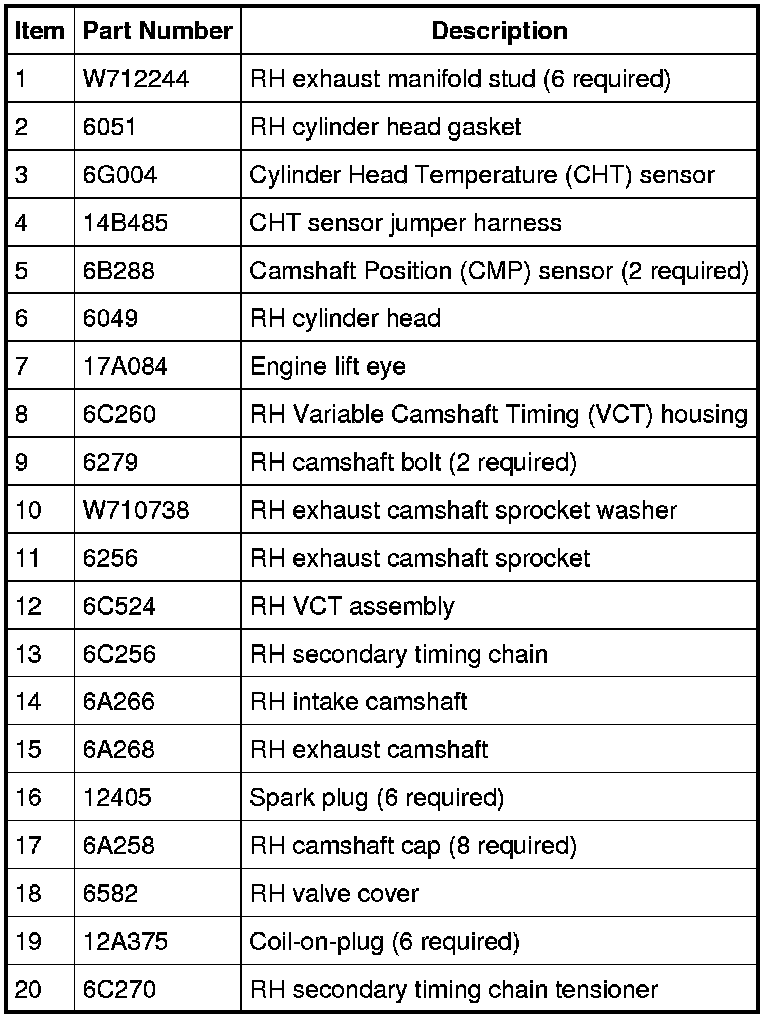
Engine Upper - RH Cylinder Head
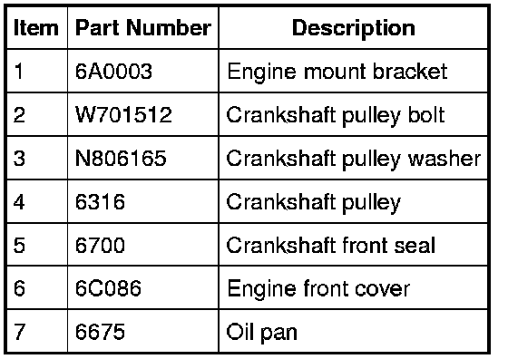
Engine Front

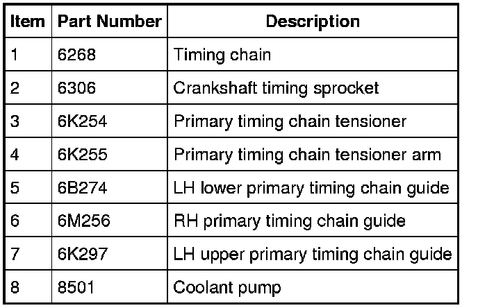
Timing Drive Components - Roller Timing Chain
NOTE: Stamped steel RH timing chain guide shown, composite guide similar.


Timing Drive Components - Inverted Tooth Timing Chain

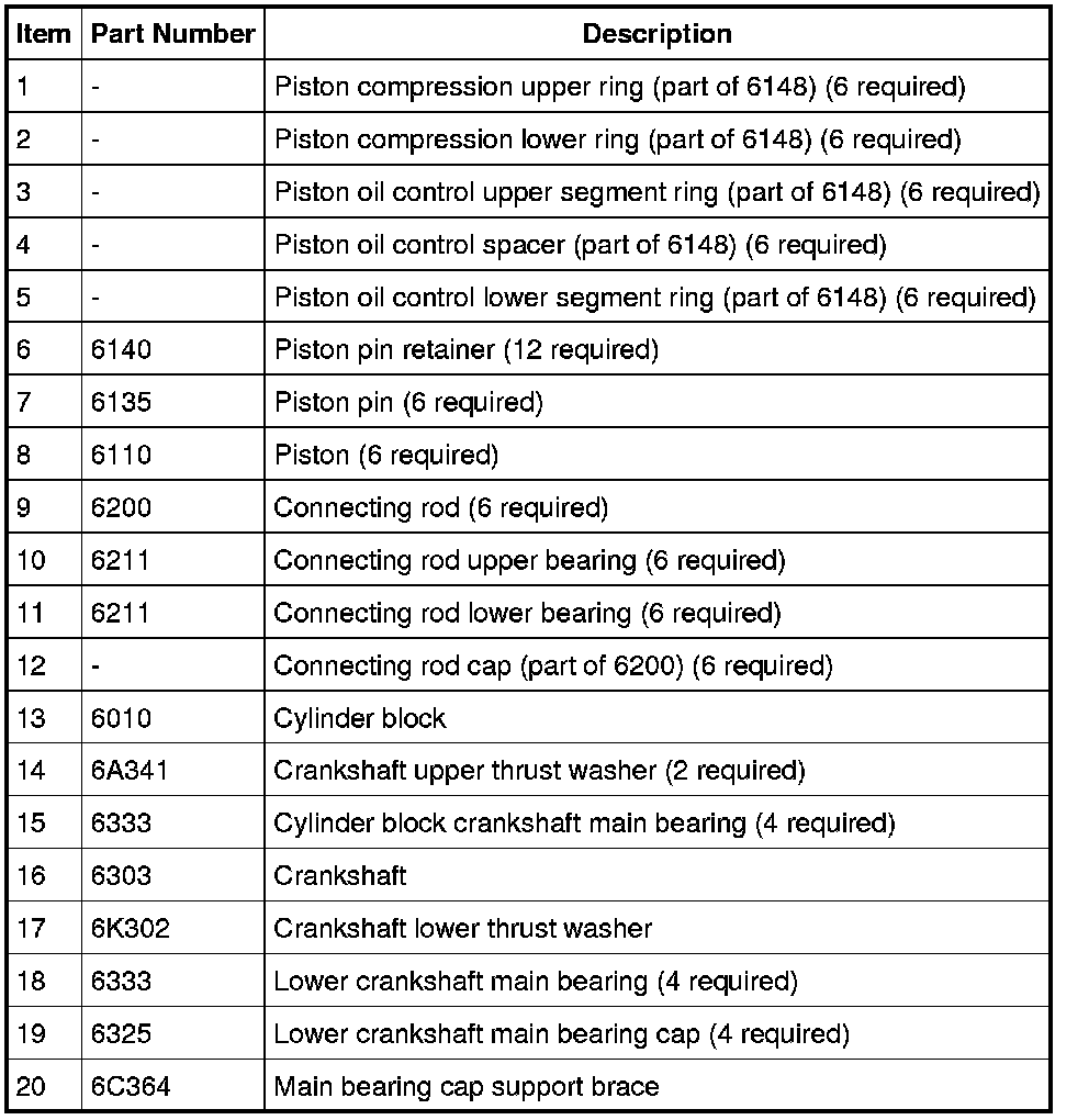
Lower Engine Block (View 1)
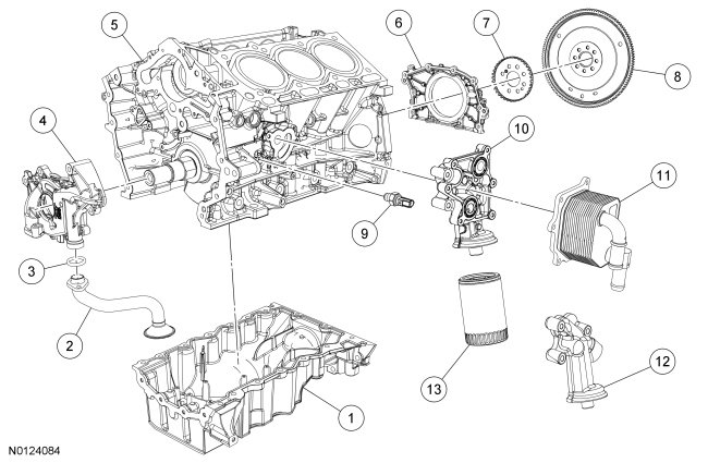
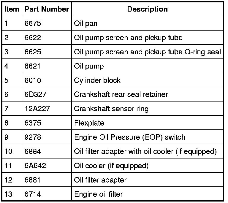
Lower Engine Block (View 2)

NOTICE: During engine repair procedures, cleanliness is extremely important. Any foreign material, including any material created while cleaning gasket surfaces that enters the oil passages, coolant passages or the oil pan, may cause engine failure.
NOTE: The engine comes equipped with either a roller primary timing chain or an inverted tooth primary timing chain. The roller timing chain engine comes equipped with either a composite RH timing chain guide requiring the timing chain to ride on the outer side of the guide or a stamped steel RH timing chain guide requiring the timing chain to ride on the inner side of the guide. All roller timing chain engine replacement RH timing chain guides will be the stamped steel design.
NOTE: Assembly of the engine requires various inspections/measurements of the engine components (engine block, crankshaft, connecting rods, pistons and piston rings). These inspections/measurements will aid in determining if the engine components will require replacement. For additional information, refer to Engine System - General Information Service and Repair.
All engines
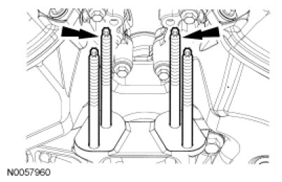
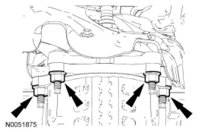
91. NOTICE: The thread sealer on the engine mount studs (including new engine mount studs if applicable) must be cleaned off with a wire brush and new Threadlock and Sealer applied prior to installing the engine mount studs. Failure to follow this procedure may result in damage to the engine mount studs or engine.
Install the engine mount studs in the following sequence.
1. Clean the front cover engine mount stud holes with pressurized air to remove any foreign material.
2. Clean all the thread sealer from the engine mount studs (old and new studs).
3. Apply new Threadlock and Sealer to the engine mount stud threads.
4. Install the 2 engine mount studs.
- Tighten to 20 Nm (177 lb-in).
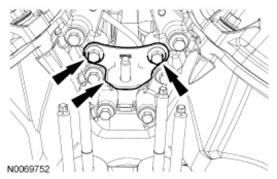
92. Install the engine mount bracket and the 2 bolts.
- Tighten to 24 Nm (18 lb-ft).
93. NOTE: Apply clean engine oil to the crankshaft front seal bore in the engine front cover.
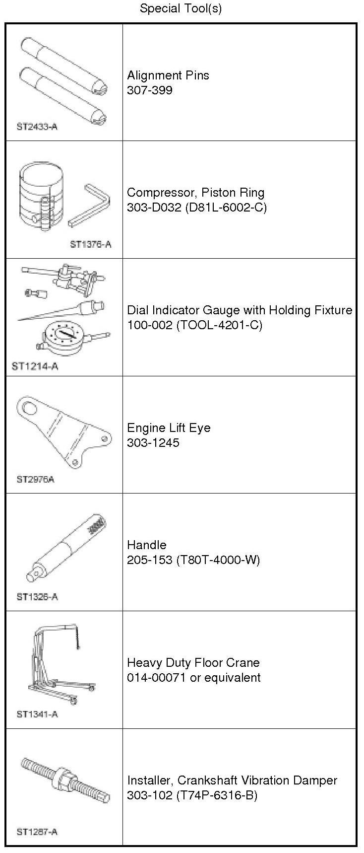
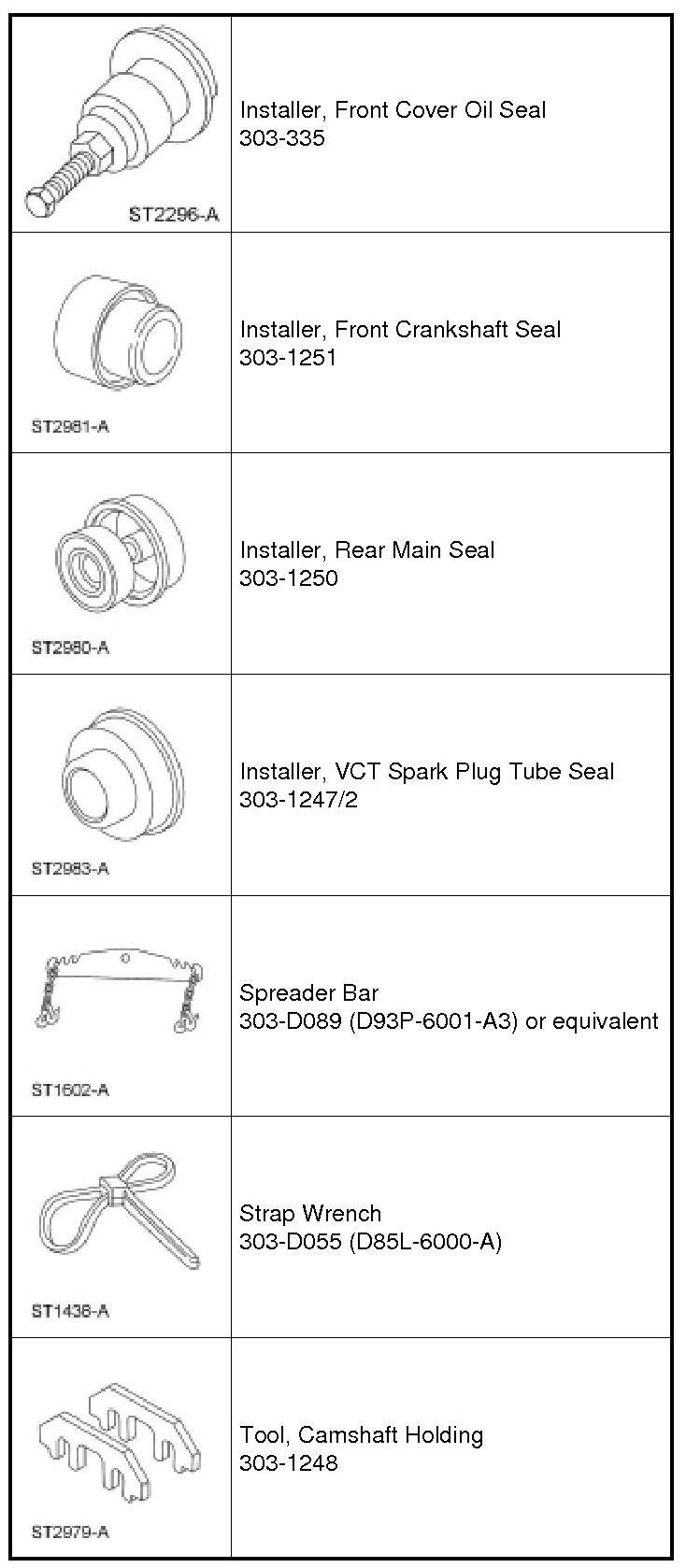
Using the Crankshaft Vibration Damper Installer and Front Crankshaft Seal Installer, install a new crankshaft front seal.

94. NOTE: Lubricate the outside diameter sealing surfaces with clean engine oil.
Using the Crankshaft Vibration Damper Installer and Front Cover Oil Seal Installer, install the crankshaft pulley.

95. Using the Strap Wrench, install the crankshaft pulley washer and new bolt and tighten in 4 stages.
- Stage 1: Tighten to 120 Nm (89 lb-ft).
- Stage 2: Loosen one full turn.
- Stage 3: Tighten to 50 Nm (37 lb-ft).
- Stage 4: Tighten an additional 90 degrees.

96. NOTE: Installation of new seals is only required if damaged seals were removed during disassembly of the engine.
NOTE: Spark plug tube seal installation shown, VCT solenoid seal installation similar.
Using the VCT Spark Plug Tube Seal Installer and Handle, install new VCT solenoid and/or spark plug tube seals.

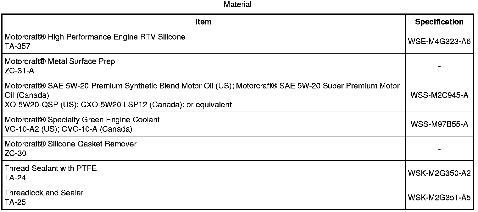
97. NOTICE: Failure to use Motorcraft(R) High Performance Engine RTV Silicone may cause the engine oil to foam excessively and result in serious engine damage.
NOTE: If the valve cover is not installed and the fasteners tightened within 4 minutes, the sealant must be removed and the sealing area cleaned. To clean the sealing area, use silicone gasket remover and metal surface prep. Failure to follow this procedure can cause future oil leakage.
Apply an 8 mm (0.31 in) bead of Motorcraft(R) High Performance Engine RTV Silicone to the engine front cover-to-RH cylinder head joints.

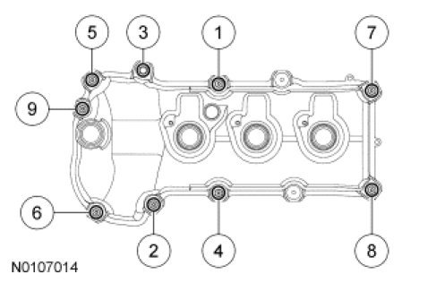
98. Using a new gasket, install the RH valve cover and tighten the bolt and 8 stud bolts.
- Tighten in the sequence shown to 10 Nm (89 lb-in).
99. NOTICE: Failure to use Motorcraft(R) High Performance Engine RTV Silicone may cause the engine oil to foam excessively and result in serious engine damage.
NOTE: If the valve cover is not installed and the fasteners tightened within 4 minutes, the sealant must be removed and the sealing area cleaned. To clean the sealing area, use silicone gasket remover and metal surface prep. Failure to follow this procedure can cause future oil leakage.
Apply an 8 mm (0.31 in) bead of Motorcraft(R) High Performance Engine RTV Silicone to the engine front cover-to-LH cylinder head joints.

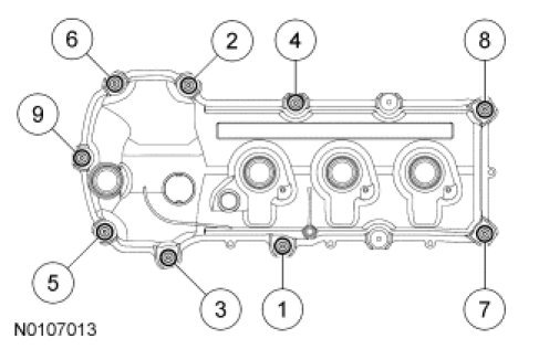
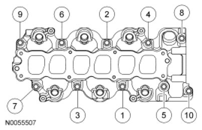
100. Using a new gasket, install the LH valve cover and tighten the 9 stud bolts.
- Tighten in the sequence shown to 10 Nm (89 lb-in).
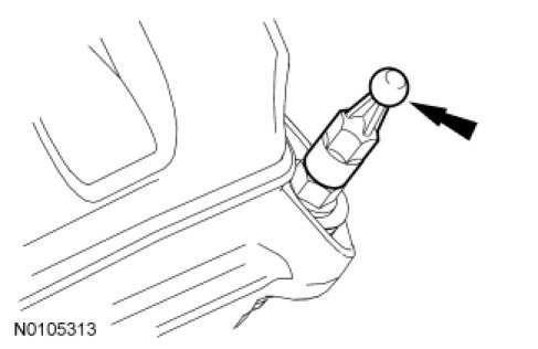
101. Install the engine cover stud on the valve cover stud bolt.
- Tighten to 6 Nm (53 lb-in).
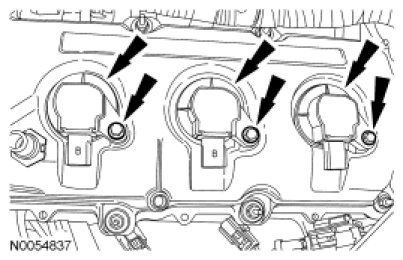
102. NOTE: LH shown, RH similar.
Install the 6 coil-on-plug assemblies and the 6 bolts.
- Tighten to 7 Nm (62 lb-in).
103. NOTE: Apply thread sealant with PTFE to the Engine Oil Pressure (EOP) switch threads.
Install the EOP switch.
- Tighten to 14 Nm (124 lb-in).

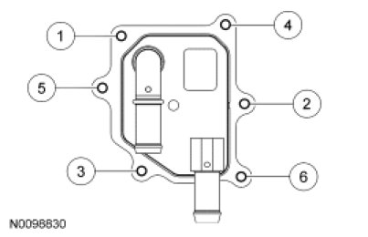
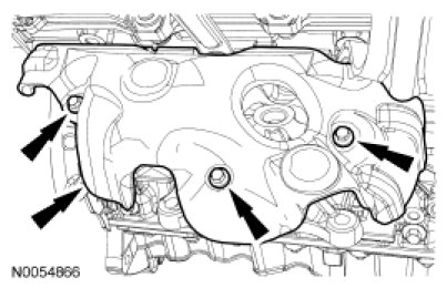
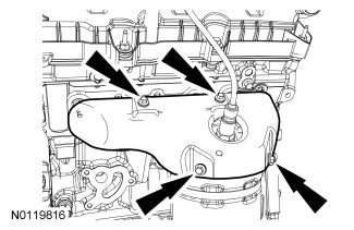
104. NOTE: Engine without oil cooler shown, engine with oil cooler similar.
Using a new gasket, install the oil filter adapter and 3 bolts.
- Tighten to 10 Nm (89 lb-in) plus an additional 45 degrees.

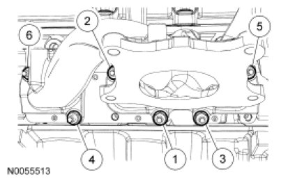
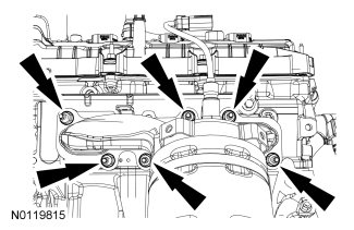
105. NOTICE: A new oil cooler must be installed or severe damage to the engine may occur.
If equipped, install a new oil cooler, new gaskets and the 6 bolts.
- Tighten in the sequence shown to 10 Nm (89 lb-in).
106. Install the Crankshaft Position (CKP) sensor and install the bolt.
- Tighten to 10 Nm (89 lb-in).

107. Install LH Camshaft Position (CMP) sensor and the bolt.
- Tighten to 10 Nm (89 lb-in).

108. Install and connect the Cylinder Head Temperature (CHT) sensor jumper harness.
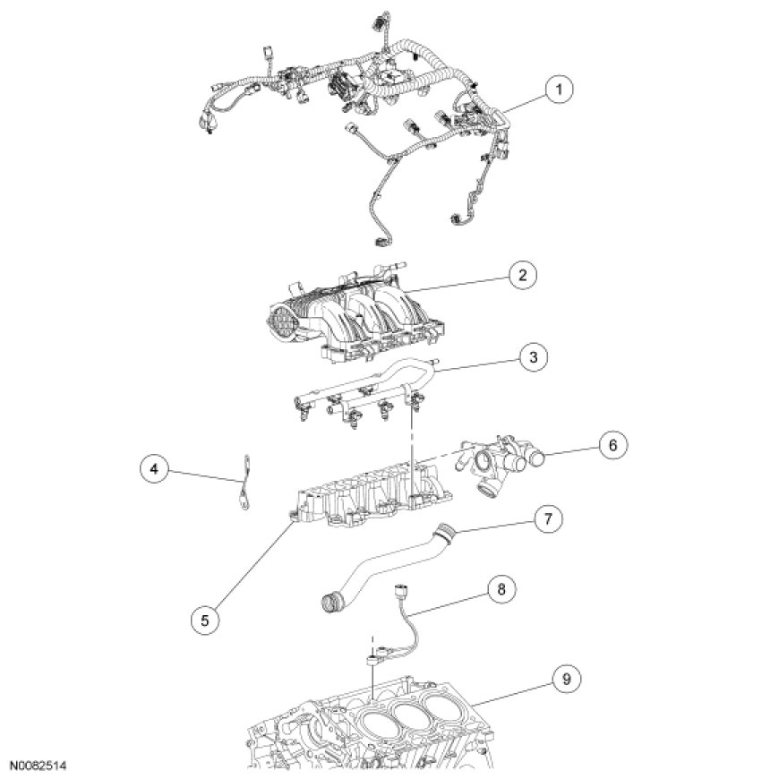
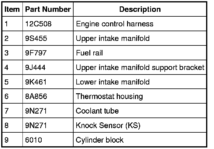
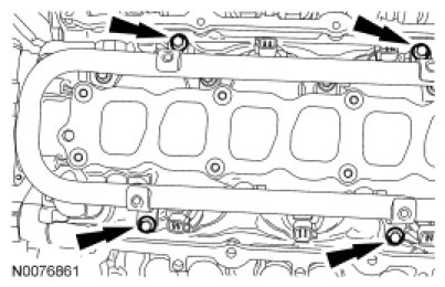
109. NOTICE: If the engine is repaired or replaced because of upper engine failure, typically including valve or piston damage, check the intake manifold for metal debris. If metal debris is found, install a new intake manifold. Failure to follow these instructions can result in engine damage.
Using new gaskets, install the lower intake manifold and the 10 bolts.
- Tighten in the sequence shown to 10 Nm (89 lb-in).
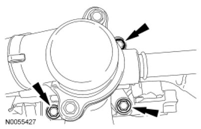
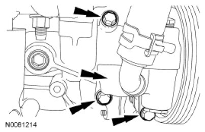
110. Using a new gasket, install the thermostat housing and the 3 bolts.
- Tighten to 10 Nm (89 lb-in).
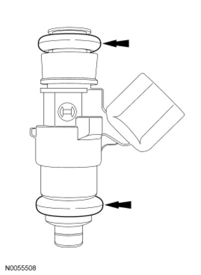
111. NOTICE: Use O-ring seals that are made of special fuel-resistant material. The use of ordinary O-rings may cause the fuel system to leak. Do not reuse the O-ring seals.
NOTE: The upper and lower O-ring seals are not interchangeable.
Install new fuel injector O-ring seals.
- Remove the retaining clips and separate the fuel injectors from the fuel rail.
- Remove and discard the O-ring seals.
- Install new O-ring seals and lubricate with clean engine oil.
- Install the fuel injectors and the retaining clips onto the fuel rail.
112. Install the fuel rail and injectors as an assembly and install the 4 bolts.
- Tighten to 10 Nm (89 lb-in).
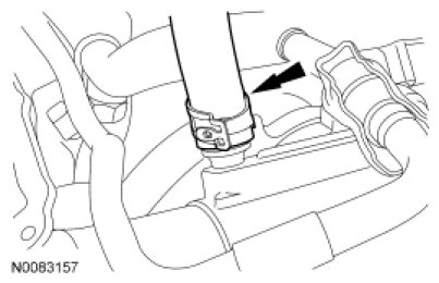
113. Install the coolant bypass hose to the thermostat housing.
114. Install the RH CMP sensor and the bolt.
- Tighten to 10 Nm (89 lb-in).

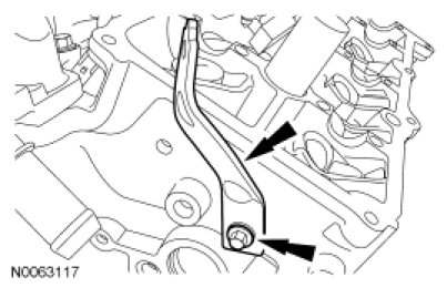
115. NOTE: Align the bracket with the index mark made during removal.
Install the upper intake manifold support bracket and the bolt.
- Tighten to 10 Nm (89 lb-in).
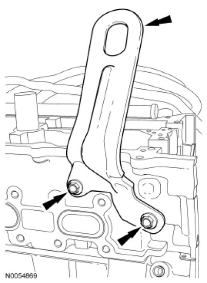
116. Install the engine lifting eye and the 2 bolts.
- Tighten to 24 Nm (18 lb-ft).
117. Install the cover and the pin-type retainer.

118. Install the LH cylinder block drain plug.
- Tighten to 16 Nm (142 lb-in) plus an additional 180 degrees.

119. Install the RH cylinder block drain plug or, if equipped, the block heater.
- Tighten the cylinder block drain plug to 10 Nm (89 lb-in) plus an additional 720 degrees.
- Tighten the block heater to 40 Nm (30 lb-ft).

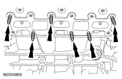
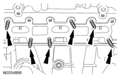
120. Install 6 new RH exhaust studs.
- Tighten to 12 Nm (106 lb-in).
121. NOTICE: Failure to tighten the exhaust manifold nuts to specification a second time will cause the exhaust manifold to develop an exhaust leak.
Using a new gasket, install the RH exhaust manifold and 6 new nuts. Tighten in 2 stages in the sequence shown:
- Stage 1: Tighten to 20 Nm (177 lb-in).
- Stage 2: Tighten to 25 Nm (18 lb-ft).
122. Install the RH exhaust manifold heat shield and the 3 bolts.
- Tighten to 10 Nm (89 lb-in).
Front Wheel Drive (FWD) vehicles
123. Using a new gasket, install the RH catalytic converter and the 4 new nuts.
- Tighten to 40 Nm (30 lb-ft).
All engines
124. Install 6 new LH exhaust studs.
- Tighten to 12 Nm (106 lb-in).
125. Using a new gasket, install the LH catalytic converter and 3 new lower LH catalytic converter manifold-to-cylinder head nuts.
- Install the 3 new upper LH catalytic converter manifold-to-cylinder head nuts and tighten to 25 Nm (18 lb-ft).
- Tighten the 3 lower LH catalytic converter manifold-to-cylinder head nuts to 25 Nm (18 lb-ft).
126. Install the LH exhaust heat shield and the 4 bolts.
- Tighten to 10 Nm (89 lb-in).
127. Install the accessory drive belt tensioner and the 3 bolts.
- Tighten to 11 Nm (97 lb-in).

128. Install the power steering pump and the 3 bolts.
- Tighten to 25 Nm (18 lb-ft).
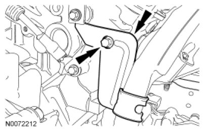
129. Install the Power Steering Pressure (PSP) tube bracket and the bolt to the RH cylinder head.
- Tighten to 10 Nm (89 lb-in).
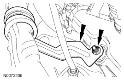
130. Install the PSP tube bracket and nut to the RH valve cover stud bolt.
- Tighten to 7 Nm (62 lb-in).
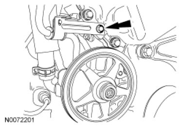
131. Install the PSP tube bracket bolt.
- Tighten to 10 Nm (89 lb-in).
132. Install the stud, generator and the nut and the bolt.
- Tighten the generator stud to 12 Nm (106 lb-in).
- Tighten nut and bolt to 48 Nm (35 lb-ft).

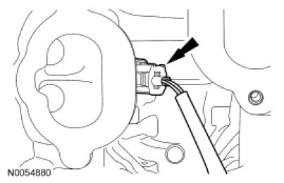
133. Position the wiring harness onto the engine.
134. Connect the EOP switch electrical connector and the wiring harness pin-type retainer.

135. Connect the generator electrical connector.
