Pinpoint Test A: The BSIA System Does Not Release/Lock Correctly
External Controls - Column Shift
Pinpoint Tests
Refer to Wiring Diagram Set 29, Transmission Controls for schematic and connector information. Diagrams By Number
Refer to Wiring Diagram Set 37, Shift Interlock for schematic and connector information. Diagrams By Number
NOTE: Refer to all TSBs and On-Line Automotive Service Information System (OASIS) messages that pertain to the transmission concern and follow the procedure as described.
NOTE: Read and record all DTCs.
Transmission Vehicle Harness - C1548


Brake Shift Interlock Actuator (BSIA) - C2008


Tow/Haul Switch - C2399


PINPOINT TEST A: THE BSIA SYSTEM DOES NOT RELEASE/LOCK CORRECTLY
NOTE: Perform a thorough inspection of the selector lever cable before proceeding with this pinpoint test.
-------------------------------------------------
A1 TEST THE BRAKE SWITCH
- Ignition ON.
- Apply the brake pedal and observe the High Mounted Stoplamp.
- Does the High Mounted Stoplamp illuminate?
Yes
GO to A2.
No
REFER to Exterior Lighting Testing and Inspection.
-------------------------------------------------
A2 TEST SJB FUSE 5 (10A)
- Check fuse: Smart Junction Box (SJB) 5 (10A).
- Is the resistance less than 5 ohms?
Yes
GO to A4.
No
GO to A3.
-------------------------------------------------
A3 CHECK CIRCUIT CDC37 (GY/VT) FOR A SHORT TO GROUND
- Disconnect: Brake Shift Interlock Actuator (BSIA) C2008.
- Disconnect: SJB C2280C.
- Inspect C2008, C2280C, C2239 and C214 for damaged or pushed-out terminals, corrosion or loose wires. Repair as necessary.
- Measure the resistance between the BSIA C2008-3, circuit CDC37 (GY/VT) harness side and ground.
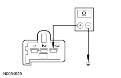
- Is the resistance greater than 10,000 ohms?
Yes
GO to A4.
No
REPAIR circuit CDC37 (GY/VT) for a short to ground. CLEAR DTCs. TEST the system for normal operation.
-------------------------------------------------
A4 CHECK CIRCUIT CDC37 (GY/VT) FOR AN OPEN
- Measure the resistance between the BSIA C2008-3, circuit CDC37 (GY/VT) and SJB C2280C-23, circuit CDC37 (GY/VT), harness side.
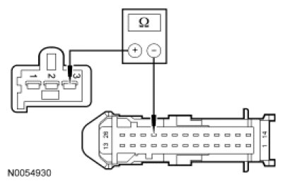
- Is the resistance less than 5 ohms?
Yes
GO to A5.
No
REPAIR circuit CDC37 (GY/VT) for an open. CLEAR DTCs. TEST the system for normal operation.
-------------------------------------------------
A5 TEST CIRCUIT GD138 (BK/WH) FOR AN OPEN
- Measure the resistance between the BSIA C2008-1, circuit GD138 (BK/WH), harness side and ground.
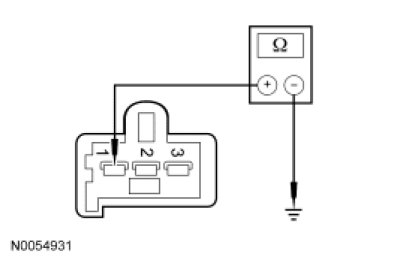
- Is the resistance less than 5 ohms?
Yes
GO to A6.
No
REPAIR circuit GD138 (BK/WH) for an open. CLEAR DTCs. TEST the system for normal operation.
-------------------------------------------------
A6 TEST CIRCUIT CDC37 (GY/VT) FOR VOLTAGE
- Connect: SJB C2280C.
- Measure the voltage between the BSIA C2008-3, circuit CDC37 (GY/VT), harness side and ground, while applying the brake pedal.
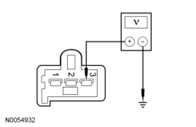
- Is the voltage greater than 10 volts with the brake pedal applied?
Yes
INSTALL a new BSIA. REFER to Brake Shift Interlock Actuator - Column Shift Brake Shift Interlock Actuator - Column Shift. CLEAR DTCs. TEST the system for normal operation.
No
INSTALL a new SJB. REFER to Module Communications Network Service and Repair. CLEAR DTCs. TEST the system for normal operation.
-------------------------------------------------