Step 3
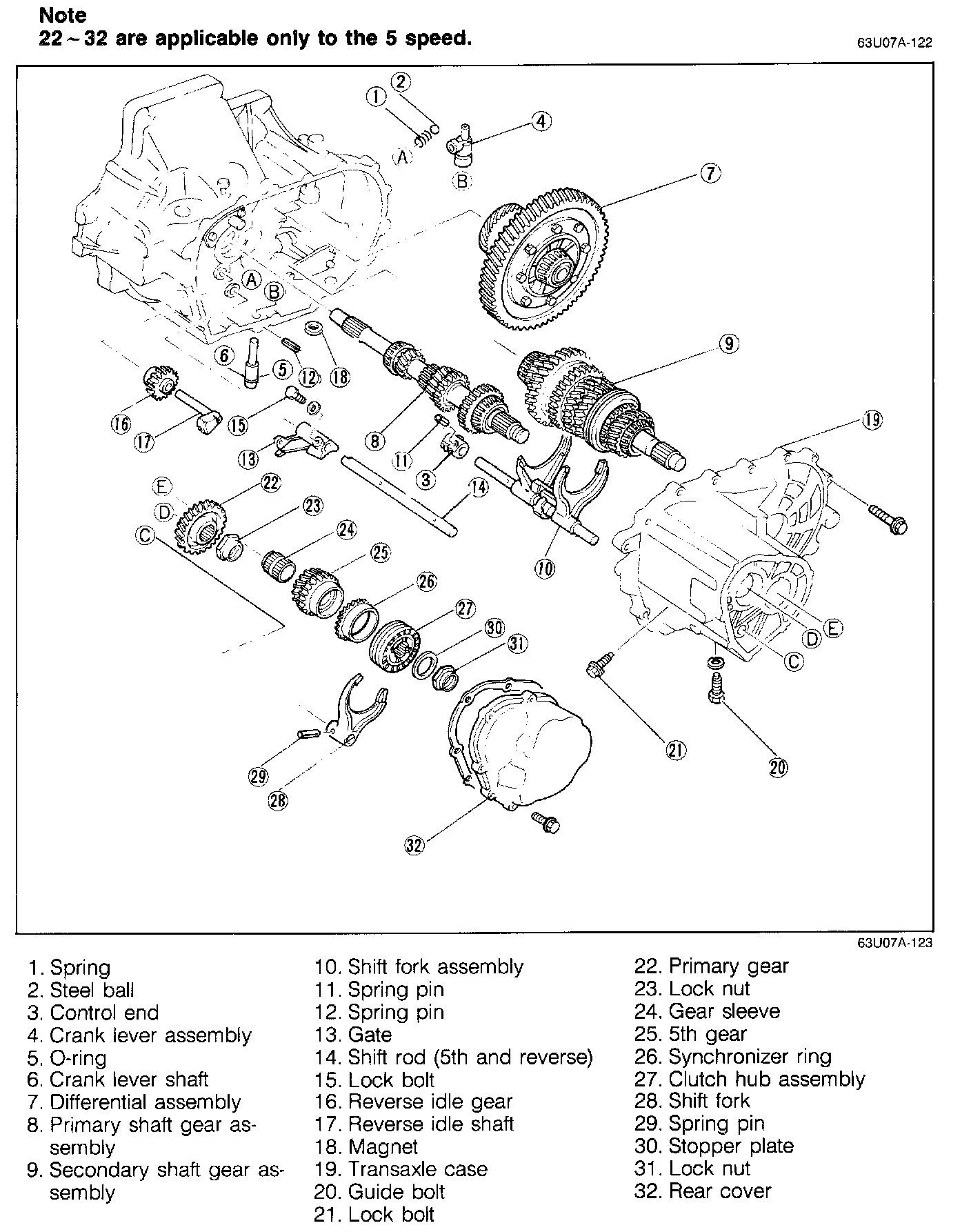
ASSEMBLY-STEP 3
Assemble in the numbered order shown in the image
Bearing Preload
Check the primary shaft gear and the differential bearing preload.
NOTE:
a. Confirm that the correct adjustment shims were selected.
b. If the bearing preload is not within the standard range, adjust again.
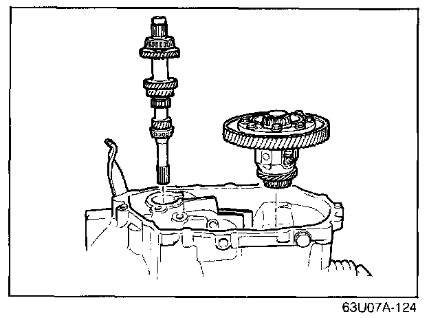
1. Install the primary shaft gear and the differential into the clutch housing.
2. Install the transaxle case, and tighten to the specified torque.
Tightening torque: 18-26 Nm (1.8-2.6 m-kg, 13-19 ft-lb)
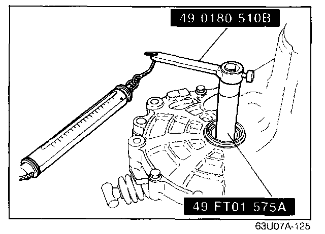
3. Connect the preload attachment (49 0180 51 0B) to the preload adaptor (49 FT01 515A), and install it through the driveshaft hole.
4. Hook a spring scale to the attachments and measure the preload.
Preload: 0.03-0.75 N.m (0.3-7.6 cm-kg, 0.26-6.6 in-lb)
Spring scale reading: 0.3-7.5 N (0.03-0.76 kg, 0.07-1.67 lb)
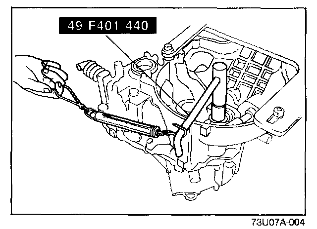
5. Remove the adaptor and the attachment.
6. With the transaxle facing in the direction shown in the image, install the primary shaft holder (49 F401 440) to the primary shaft gear. Hook the spring scale to the holder and measure the preload.
Preload: 0.10-0.34 Nm (1.0-3.5 cm-kg, 0.87-3.0 in-lb)
Spring scale reading: 0.54-1.84 N (54-190 g, 0.12-0.41 lb)
NOTE: Extend the handle fully and hook the pull scale to the end of the handle.
Shaft Gear and Shift Fork Assembly
Install the primary shaft gear, secondary shaft gear, and shift fork assembly according to the following procedures:
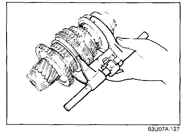
1. Install the shift fork assembly on the secondary shaft gear assembly.
NOTE: Be careful of the rod direction.
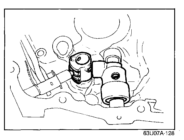
2. Assemble the control end, ball, spring, and crank lever to the clutch housing as shown in the image
CAUTION: Be careful not to lose the ball and spring.
3. Install the differential assembly.
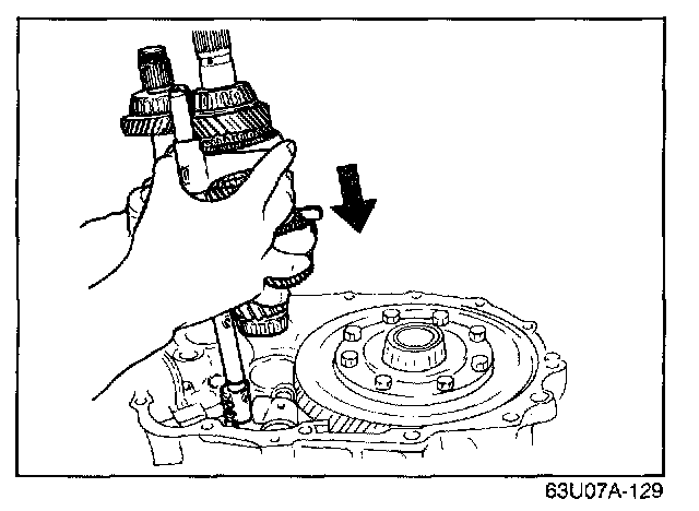
4. Unite the primary shaft gear, secondary shaft gear and shift fork assembly. Install the control rod into the control end as the unit is lowered into place.
NOTE: Keep the assembly nearly vertical while installing it.
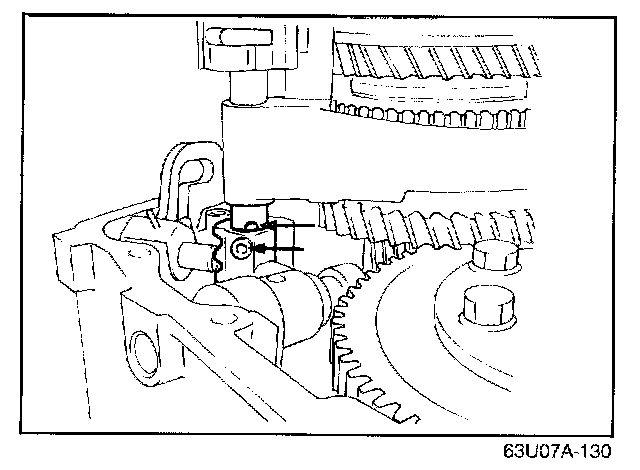
5. Align the holes in the control rod and the control end.
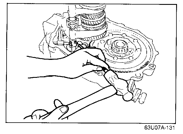
6. Tap the spring pin in with a pin punch and hammer.
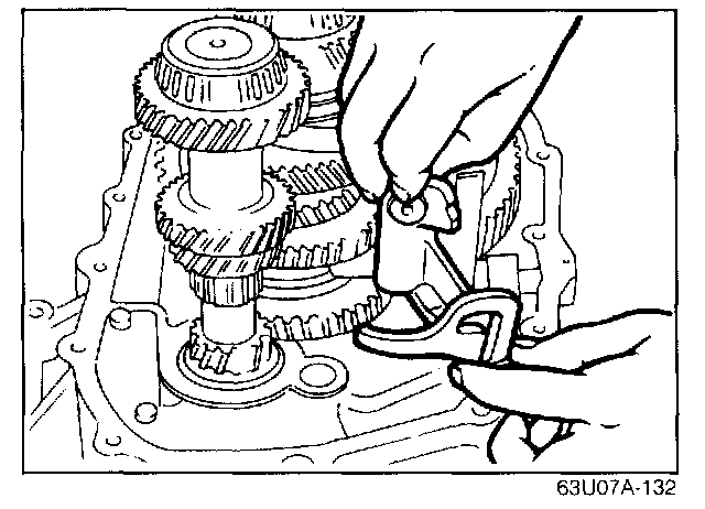
Gate (4 speed)
Raise the reverse lever and install the gate in Its groove and guide pin.
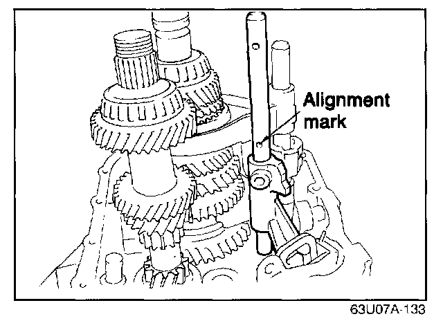
Shift Rod (5th and reverse)
When installing the shift rod (5th and reverse), make sure that the alignment mark on the rod is in the correct position.
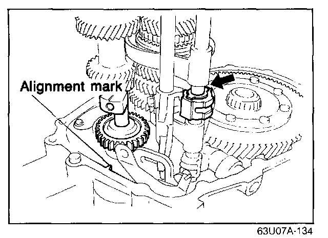
Interlock Sleeve and Reverse Idle Shaft
Before installing the transaxle case make sure the control lever (arrow) is kept flush with the surface of the end of the interlock sleeve. Point the threaded hole of the reverse idle shaft toward the alignment mark of the clutch housing.
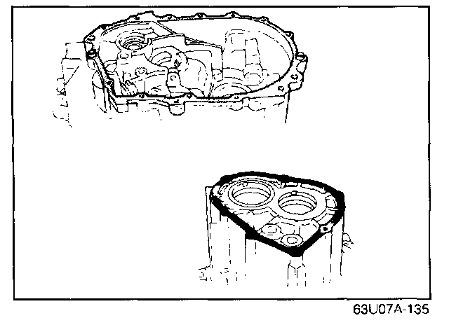
Sealant
Coat sealant sparingly onto the mating surfaces of the case and housing, and the case and rear cover.
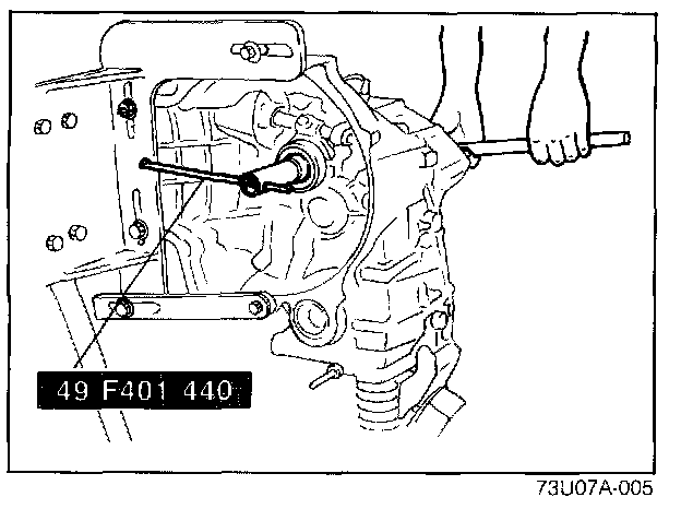
Lock Nut (primary gear)
Lock the shaft with the primary shaft holder (49 F401 440) before tightening the locknut, Use a new locknut and lighten it to the specified torque. Stake the locknut to the groove in the primary shaft.
Tightening torque: 128-206 Nm (13-21 m-kg, 94-152 ft-lb)
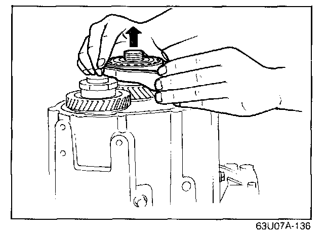
Shift Fork (5th gear)
Install the shift fork together with the clutch hub assembly.
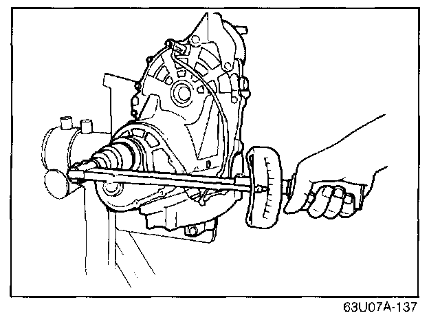
Lock Nut (5th clutch hub)
Put the transaxle in 1st or 2nd gear and lock the primary shaft with the primary shaft holder (49 F401 440) and tighten the locknut on the secondary shaft to the specified torque. Stake the locknut to the groove in the secondary shaft.
Tightening torque: 127-206 Nm (13-21 m-kg, 94-152 ft-lb)
5th Gear End Play
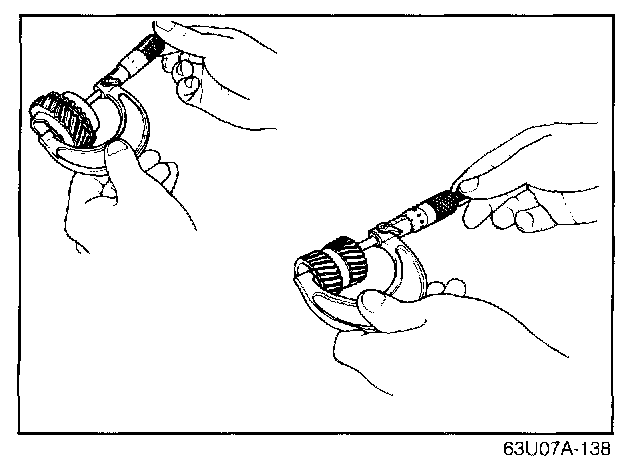
Measure the width of both the gear sleeve and the 5th gear.
The 5 the gear end play equals the difference between the gear sleeve and the 5th gear.
Standard: 0.15-0.262 mm (0.006-0.010 in)
Limit: 0.31 mm (0.012 in)