Engine Control Module: Testing and Inspection
Fig. 6 Control unit test terminal locations.:
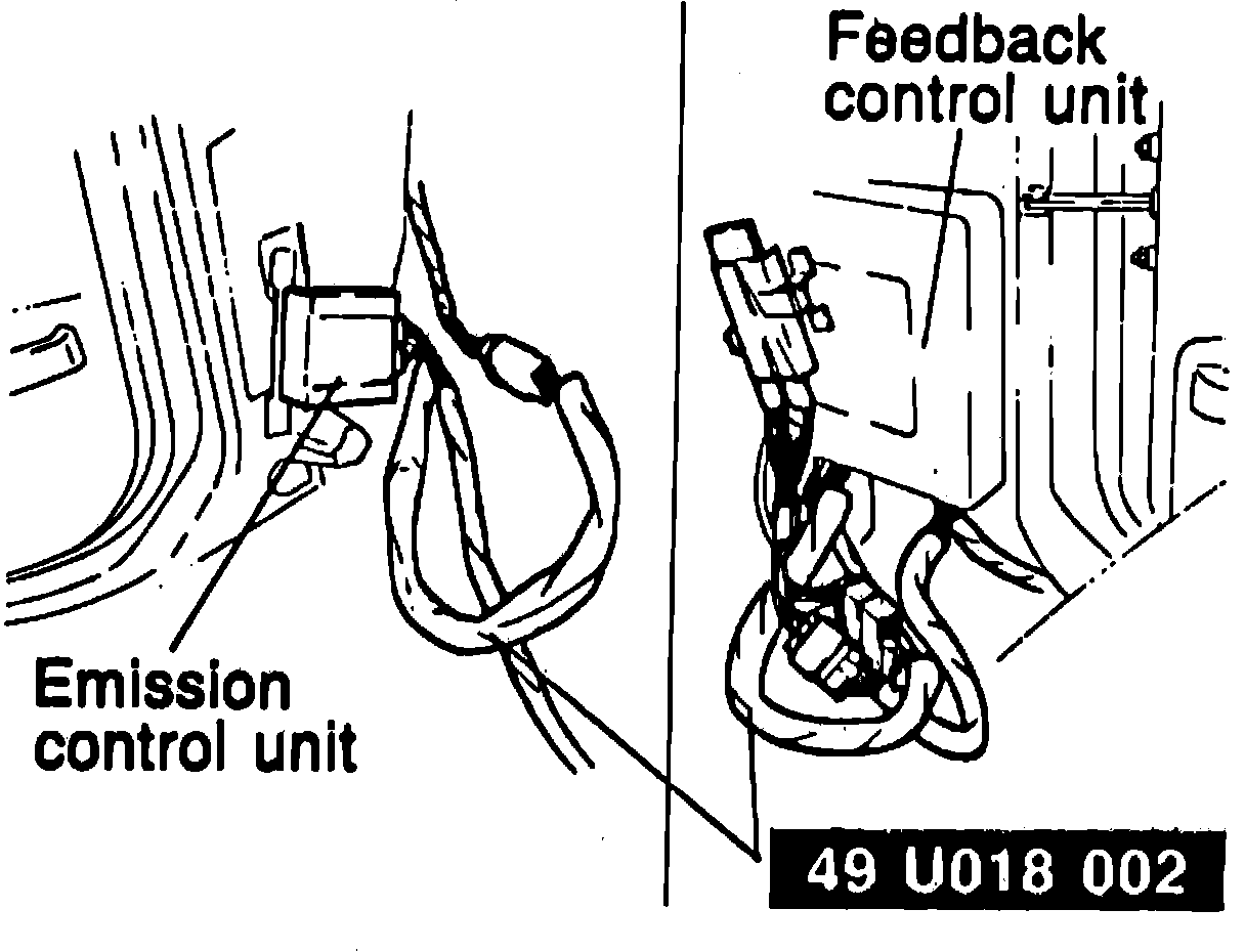
1. Run engine until normal operating temperature is reached.
2. Connect engine signal monitor 49 9200 162 and adapter 49 U018 002 to emission control unit and feedback control unit, Fig. 6.
Fig. 7 Control unit test specifications chart.:
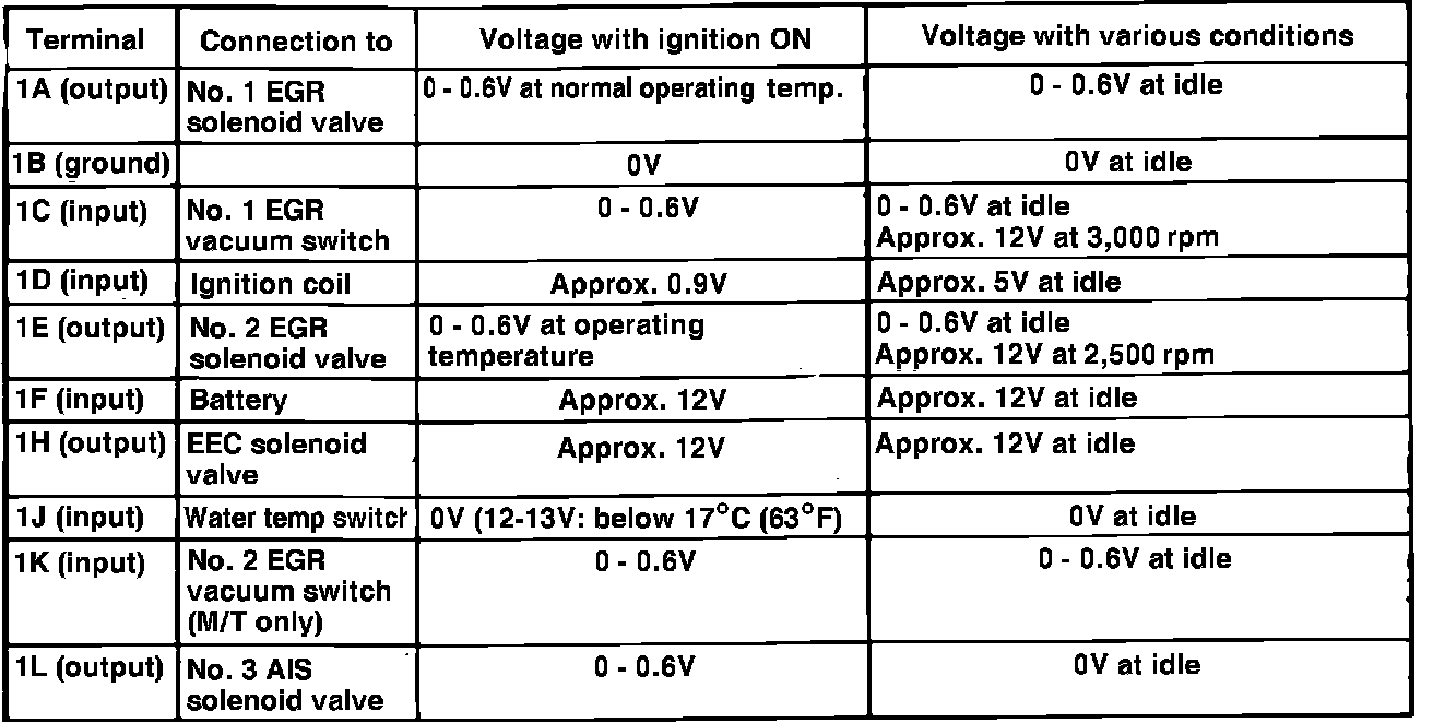
Fig. 7 Control unit test specifications chart.:
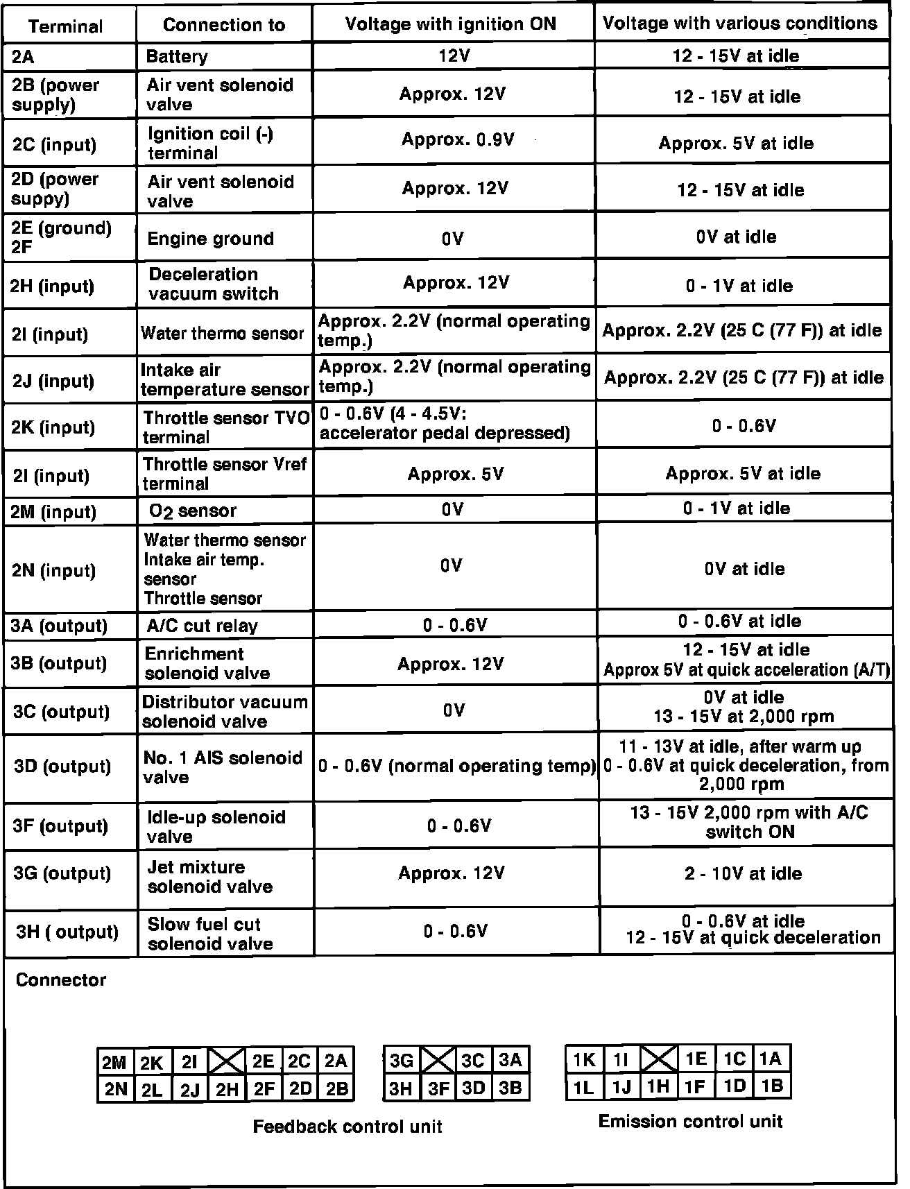
3. With ignition switch On and engine not running, measure voltage at each terminal and compare values listed in Fig. 7.
Fig. 9 Feedback control system wiring diagram.:
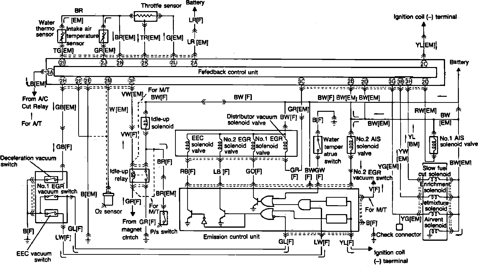
4. Refer to Fig. 9 for terminal locations.
5. If specified voltage is not obtained, check wiring, electrical connectors and related component(s) and correct as necessary.