Assembly
Fig. 89 Piston Ring Locations:

Refer to DISASSEMBLY, reverse procedure to assemble, noting the following:
1. Assemble piston and connecting rod with identification marks facing upward.
2. Install piston ring as follows:
a. Install oil ring spacer with ends upward, then the upper and lower rails. Ensure rails turn smoothly in both directions.
b. Install rings to piston. Rings must be installed with R marks upward. Second ring must be installed with scraper face downward.
3. Position ring end gaps as shown in Fig. 89.
Fig. 90 Main Bearing Cap Bolt Tightening Sequence:

4. Install main bearing caps according to cap number and arrow mark. Torque main bearing cap bolts in three steps in sequence shown in Fig. 90, to 40-43 ft. lbs.
5. Install connecting rod caps with matching marks aligned. Torque connecting rod cap nut in three steps to 36-38 ft. lbs.
Fig. 92 Valve Spring Installation:

6. On all models, Install valve spring with narrow pitch end toward cylinder head, Fig. 92.
Fig. 93 Cylinder Head Tightening Sequence.:
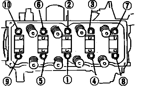
7. Torque cylinder head bolts in three steps in sequence shown in Fig. 93, to 56-60 ft. lbs.
Fig. 96 Rocker Shaft Tightening Sequence:
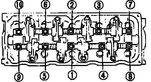
8. Torque rocker shaft bolts in three steps in sequence shown in Fig. 96, to 16-21 ft. lbs.
9. Install cylinder head cover with new seal washers.
10. On all models, assemble timing belt, refer to TIMING BELT.