Exhaust Gas Recirculation: Testing and Inspection
SYSTEM INSPECTION
NOTE: Troubleshoot with the Self-Diagnosis Checker before performing the following steps. Check the condition of the wiring harness and/or vacuum lines and connectors before checking the sensors or switches.
1. Check the vacuum hose routing.
2. If incorrect connection, clogging, or leakage is found, repair or replace the hose.
3. Warm up the engine and run it at idle.
Disconnecting EGR System:

4. Disconnect vacuum the hose from the EGR control valve and plug it.
5. Verify that the engine runs smoothly.
6. If it does not, check the EGR control valve.
Measuring EGR Vacuum:
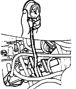
7. Connect a vacuum gauge to the EGR hose.
8. Verify that the gauge shows no vacuum.
9. Accelerate the engine, and verify that the gauge shows vacuum.
10. Decelerate the engine, and verify that the gauge again shows no vacuum.
11. If a problem is found, check the duty solenoid valve and the "2L" and "2K" terminals of the engine control unit.
NOTE: The engine control unit is located behind the passenger kick panel.
Measuring EGR Vacuum:
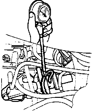
12. Connect a vacuum gauge between the duty solenoid valve and the EGR control valve, as shown.
13. Accelerate the engine, and note the amount of vacuum.
14. Disconnect vacuum hose at the EGR valve and plug it.
15. Accelerate and verify that the gauge shows higher vacuum than in step 13.
16. If it does not, check the EGR position sensor, the "1F" terminal of the engine control unit, and the duty solenoid valve.
Jumpering Coolant Temperature Switch Harness:
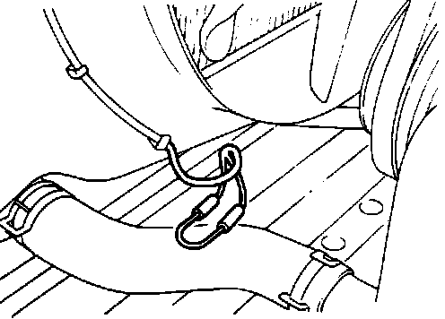
17. Disconnect the connectors from the water temperature switch, and connect them with a jumper wire.
18. With vacuum hose "A" plugged, verify that the gauge shows no vacuum when the engine is accelerated.
19. If it shows vacuum, check the duty solenoid valve and the 1Q terminal of the engine control unit.
EGR CONTROL VALVE
Disconnecting EGR System:
1. Warm up the engine and run it at idle.
2. Disconnect the vacuum hose from the EGR control valve and plug the hose.
3. Verify that the engine runs smoothly.
4. If it does not, clean the exhaust gas passage in the valve or replace the valve.
NOTE: Before replacing the EGR control valve, check the intake air and control systems.
Vacuum Pump Connection:

5. Connect a vacuum pump to the valve, and apply vacuum.
6. Verify that the engine runs roughly or stops at more than 40-60 mmHg (1.57-2.36 in.Hg) of vacuum.
7. If it does not, replace the EGR control valve.
Tightening torque: 8-11 N-m (0.8-1.2 m-kg, 6-8 ft-lb)
Checking EGR Position Sensor Resistance:

EGR POSITION SENSOR RESISTANCE INSPECTION
1. Disconnect the sensor connector.
2. Remove the rubber boot from the connector.
3. Check resistance between the terminals while applying 0-150 mmHg (0-5.9 in.Hg) vacuum to the EGR control valve, using a vacuum pump.
Terminals Resistance
B-C 5 kOhms
A-C 5.5-0 kOhms
A-B 0.7-6.0 kOhms
Checking Vent Valve:

DUTY SOLENOID VALVE VENT VALVE INSPECTION
1. Disconnect the vacuum hoses.
2. Blow through the vent hose and verify that air passes.
3. Disconnect the duty solenoid valve connector.
4. Apply battery power and ground the solenoid valve as shown.
5. Blow through the vent hose and verify that air does not flow.
6. If a problem is found, replace the duty solenoid valve.
Checking Vacuum Valve:

DUTY SOLENOID VALVE VACUUM VALVE INSPECTION
1. Disconnect the vacuum hoses.
2. Blow through the vacuum hose and verify that air does not flow.
3. Disconnect the duty solenoid valve connector.
4. Apply battery power and ground the solenoid valve as shown.
5. Blow through the vacuum hose and verify that air passes.
6. If a problem is found, replace the duty solenoid valve.
Checking Duty Solenoid Valve Connector:

DUTY SOLENOID VALVE VOLTAGE INSPECTION
1. Remove the rubber boot from the connector.
2. Turn the ignition switch ON.
3. Using a voltmeter, verify that voltage at each terminal is approximately 12V.
4. If on any terminal it is not, check the duty solenoid valve, the wiring of the valve, and the "2C" and "2D" terminals of the engine control unit.