General System Description
System Description:
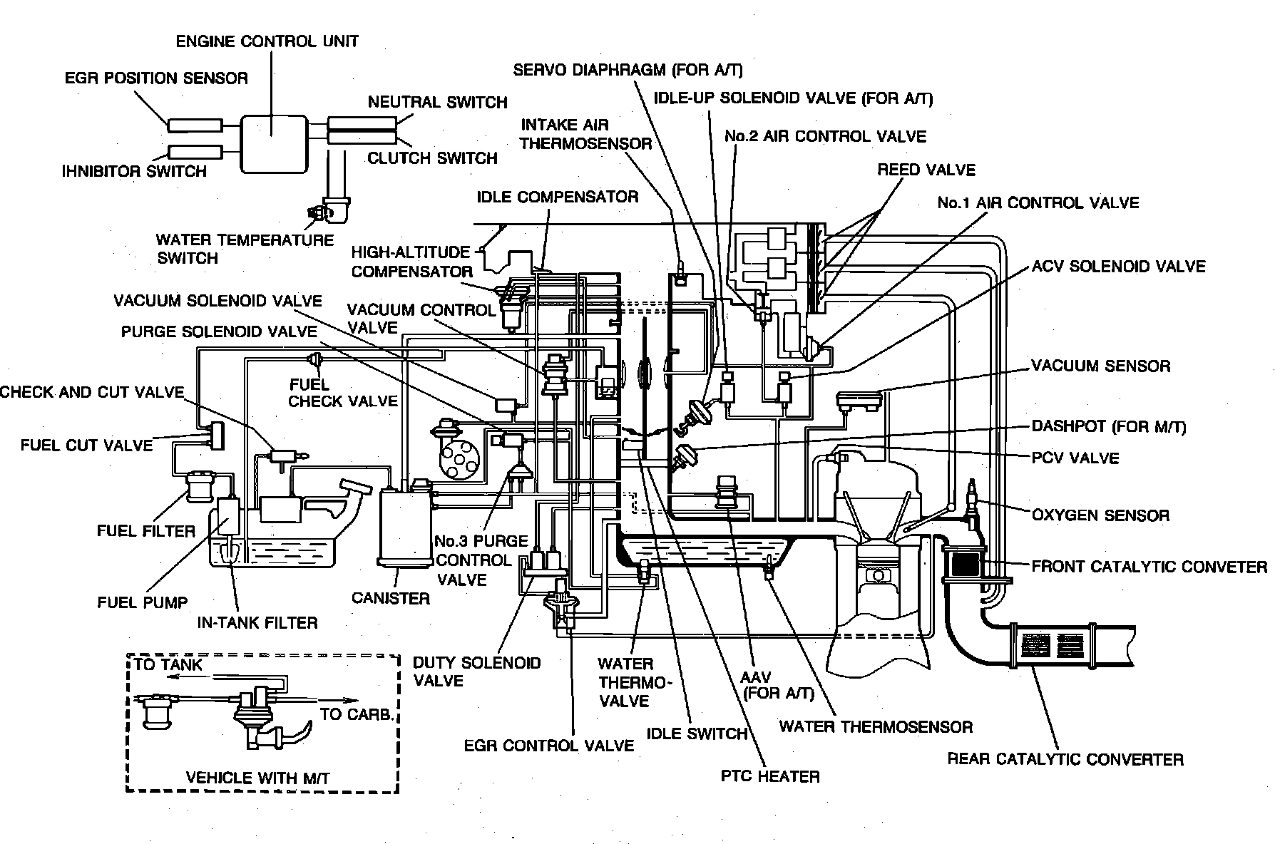
The Engine Control Unit (ECU) is the central component of this computerized fuel, ignition and emission control system. It is a carburetor feedback system featuring an ECU controlled air/fuel solenoid. To maintain fuel economy, good driveability and reduced vehicle emissions, the ECU monitors data from various sensors and controls functions such as air/fuel ratio, emission control devices and on-board diagnostics.
The ECU is a computer that judges air/fuel ratio as rich or lean according to a voltage signal generated by an oxygen sensor. Based on oxygen sensor and other input data, the ECU generates a controlling signal to the air/fuel solenoid. The ECU regulates the opening duration (duty cycle) of the air/fuel solenoid, maintaining the mixture close to the stoichiometric ratio (14.7:1) and suitability to prevailing driving conditions.
To provide a margin of safety by maintaining driveability in the event of certain system failures, the ECU has a fail-safe mode of preprogrammed values. The output of the ECU will automatically switch to fail-safe mode if a fault is detected in any of these components and/or systems:
Atmospheric pressure sensor
EGR position sensor
Feedback system
Oxygen sensor
Vacuum sensor
Water thermosensor
The system incorporates self-diagnostic capability monitored via a dash mounted malfunction indicator lamp (MIL). When the system detects a fault in a monitored component and/or circuit, the lamp will light ("CHECK") and stay on (while the engine is running), alerting the driver to seek service. The technician can then extract trouble codes from the ECU to aid in the performance of efficient troubleshooting and repair.
Components can be grouped as ECU input and output devices. Input devices control or produce voltage signals monitored by the ECU. Output devices are components controlled by the ECU. Not all of these devices are monitored by the on-board diagnostic system.
INPUT DEVICES
A/C switch
Atmospheric pressure sensor (code 14)
EGR position sensor (code 16)
Feedback system (code 17)
Idle switch
Ignition pulse (code 01)
Inhibitor switch (A/T)
Intake air thermosensor
Neutral and clutch switches (M/T)
Oxygen sensor (code 15)
Test connector
Vacuum sensor (code 13)
Water thermosensor (code 09)
OUTPUT DEVICES
Air control solenoid valve (code 30)
Air/fuel solenoid valve (code 18)
Coasting advance solenoid valve (code 45)
Coasting richer solenoid valve (code 23)
EGR duty solenoid vacuum valve (code 28)
EGR duty solenoid vent valve (code 29)
Idle-up solenoid valve (for A/C, code 34)
Idle-up solenoid valve (for A/T, code 35)
Malfunction indicator lamp (MIL)
Purge control solenoid valve (code 26)
Slow fuel cut solenoid valve (code 22)