Intake Manifold: Service and Repair
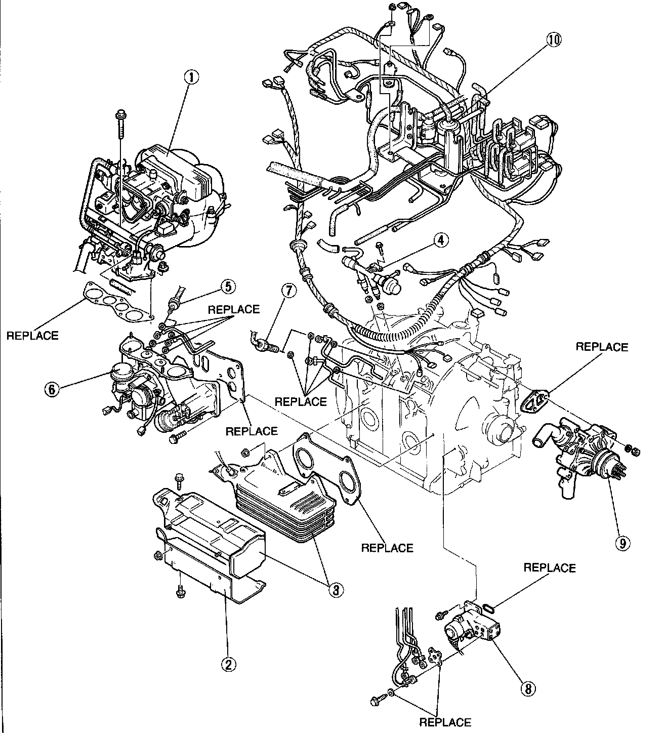
INTAKE MANIFOLD REMOVAL
1. Throttle and dynamic chamber
2. Exhaust absorber plate
3. Exhaust manifold and insulator
4. Fuel injectors and delivery pipe
5. Manifold oil nozzles and metering oil tubes
6. Intake manifold
7. Housing oil nozzles and metering oil tube
8. Engine harness and vacuum piping
Caution: Cover the intake manifold ports with a clean cloth to prevent dust or dirt from entering after the dynamic chamber is removed.
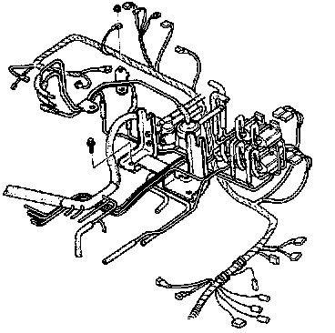
Disassembly Note: Engine harness and vacuum piping
Remove the engine harness and vacuum piping as an assembly.
INSTALLATION
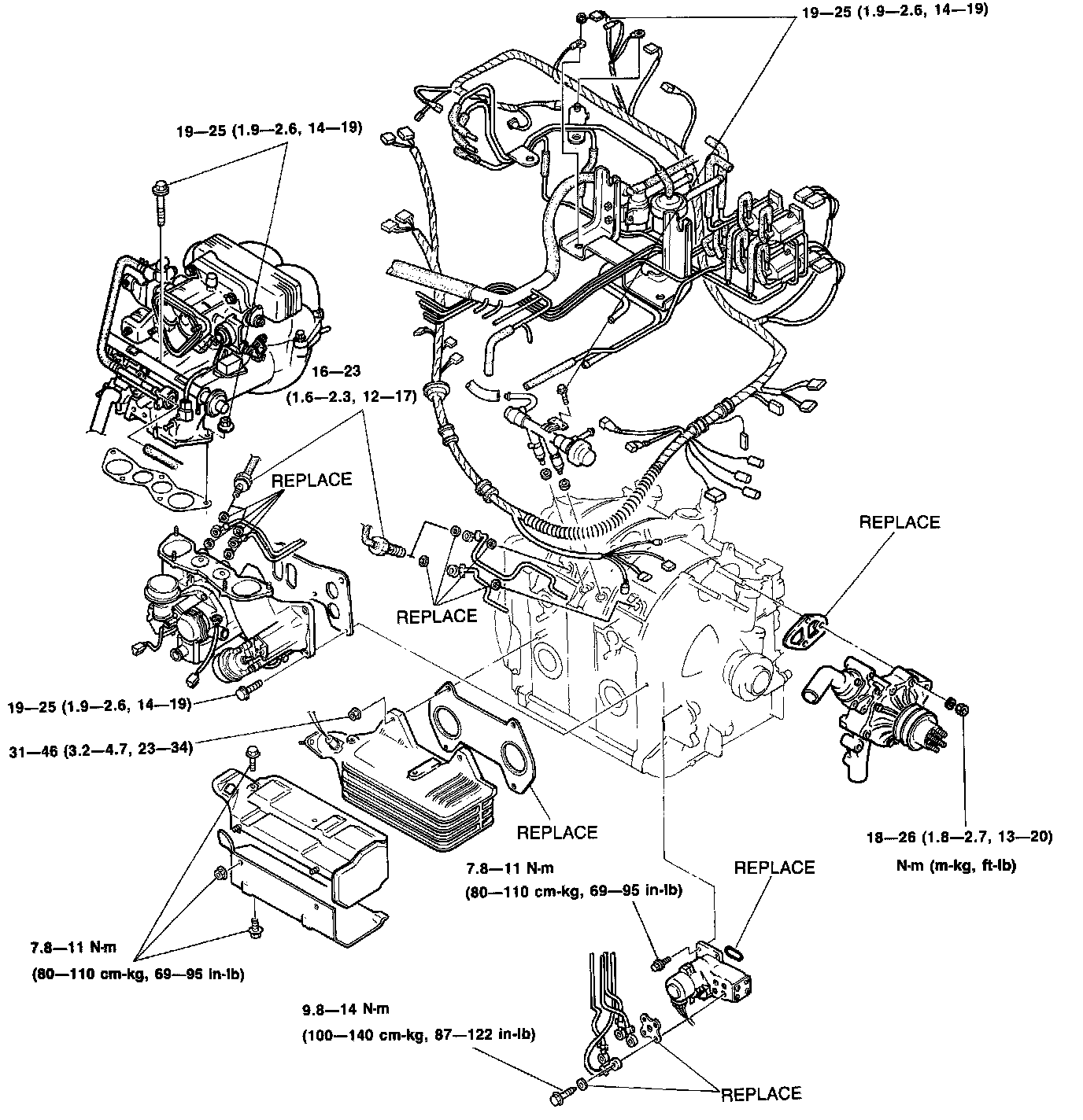
Torque Specifications
Engine Harness and Vacuum Piping
1. Connect the evaporate hose to the intermediate housing.
2. Install the engine harness and vacuum piping as an assembly and loosely tighten bolts.
Note: Finally tighten the bolts after the fuel injector and delivery pipe installation.
3. Connect the heat gauge unit connector and ground.
4. Connect the hoses to oil filler pipe.
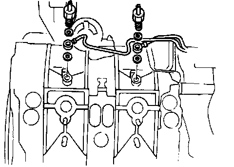
Housing Oil Nozzle and Metering Oil Tube
Install the housing oil nozzle and the oil tube and new washers to the front and rear rotor housing.
Tightening torque: 16-23 N.m (1.6-2.3 m-kg, 12-17 ft-lb)
Note: The oil tube ends are colored. For front housing White For rear housing Yellow.
Intake Manifold
1. Install the new intake manifold gasket on the engine.
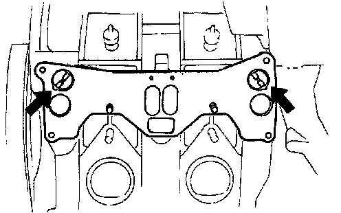
2. Install the auxiliary port valves so that the bigger side of the pin is aligned to the matching mark.
3. Install the intake manifold.
Tightening torque: 19-25 N.m (1.9-2.6 m-kg, 14-19 ft-lb)
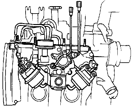
4. Connect the couplers of the split air solenoid valve and port air solenoid valve.
5 Connect the vacuum pipes.
Fuel Injector and Delivery Pipe
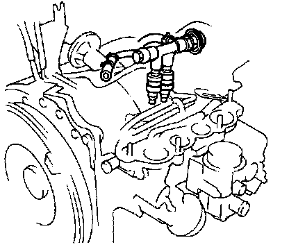
1. Insert the air bleed socket and rubber insert to the injector holes.
2. Apply engine oil to the injector 0-rings, and install the fuel injectors.
3. Install the fuel delivery pipe.
Tightening torque: 19-25 N.m (1.9-2.6 m-kg, 14-19 ft-lb)
4. Tighten the vacuum piping mounting bolts.
Tightening torque: 19-25 N.m (1.9-2.6 m-kg, 14-19 ft-lb)
Manifold Oil Nozzle and Metering Oil Tube
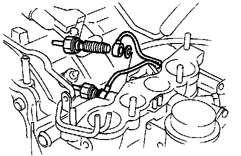
Install the manifold oil nozzle and the oil tube and new washers to the intake manifold.
Note: The oil tube ends are colored. For front port Blue For rear port Green
Tightening torque: 16-23 N.m (1.6-2.3 m-kg, 12-17 ft-lb)
Air Tube
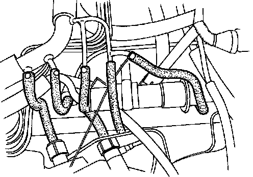
Connect the hoses to the oil nozzles.
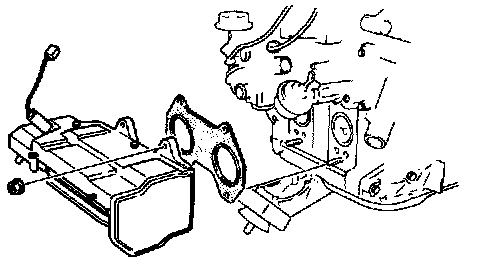
Exhaust Manifold and Insulator
1. Install the exhaust manifold and insulator and a new gasket.
Tightening torque: 31-46 N.m (3.2-4.7 m-kg, 23-34 ft-lb)
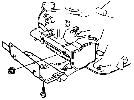
2. Install the absorber plate.
Tightening torque: 7.8-11 N.m (80-110 cm-kg, 69-95 in-lb)
3. Connect the coupler to the oxygen sensor.
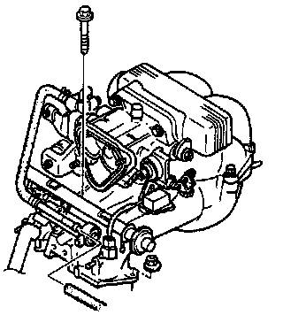
Throttle and Dynamic Chamber
1. Install the throttle and dynamic chamber assembly and a new gasket.
Tightening torque: 19-25 N.m (1.9-2.6 m-kg, 14-19 It-lb)
2. Connect the vacuum hoses, water hoses, and fuel hose.
3. Connect the couplers of the secondary injectors, throttle sensor, air bypass solenoid valve, bypass air control valve, and intake air temperature sensor.
Metering Oil Tube
Connect the oil tubes so that the colors of the tube ends match the numbers as shown. 1 White, 2 Blue, 3 Green, 4 Yellow
Tightening torque: 9.8-14 N.m (100-140 cm-kg, 87-122 in-lb)
Accelerator cable Adjustment, Refer to Throttle Cable Linkage. Throttle Cable/Linkage