Vehicle Speed Sensor 2 (Speedometer Sensor)
SpeedometerInspection
NOTE: Vehicle speed sensor 2 is a kind of generator of alternating current. Therefore, general circuit tester of direct current can not follow if the vehicle speed is fast. (If using circuit tester of alternating current, voltage Increase when the vehicle speed Is Increasing.)
1. Remove the combination meter.
2. Disconnect the speedometer connector (white).
NOTE: Set the voltmeter to the 5 V range.
3. Turn the ignition switch to LOCK position.
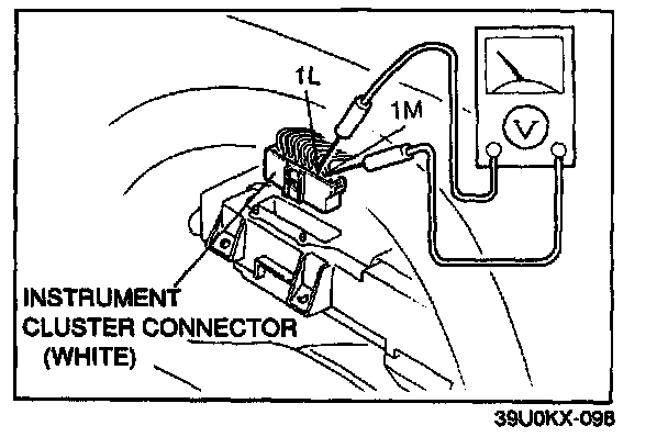
4. Measure the voltage between terminals 1L and 1M of the speedometer connector (harness side) with the rear wheels turning slowly.
5. When the voltmeter pointer moves slightly, replace the speedometer.
If the pointer does not move, check the vehicle speed sensor 2 and/or wiring.
6. Connect the speedometer connector (white)
7. Install the combination meter.
Vehicle speed Sensor 2
Inspection

1. Disconnect the negative battery cable.
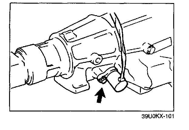
2. Remove the vehicle speed sensor 2.
3. Verify that magnetic resistance is felt when turning the vehicle speed sensor 2 driven gear by hand.
4. Remove the front exhaust pipe (left side).
5. Disconnect the vehicle speed sensor 2 connector.
NOTE: Set the voltmeter to the 5 V range.
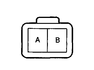
6. Measure the voltage between terminals A and B with the rear wheels turning slowly.
7. If the pointer does not move, check the vehicle speed sensor 2 continuity.
8. Measure the resistance between terminals A and B.
Resistance: Approx. 290 Ohms (at 20 °C, 68 °F)
9. It not correct, replace the vehicle speed sensor 2.
10. Apply ATF to a new O-ring and Install it on the vehicle speed sensor 2.
11. Install the vehicle speed sensor 2.
Tightening torque: 5.0 - 6.8 N.m (50 - 70 kgf.cm, 44 - 60 in.lbf)
12. Connect the vehicle speed sensor 2 connector.
13. Install the front exhaust pipe.
14. Connect the negative battery cable.