A/C Spring Lock Coupler - Cleaning Tips
Bulletin No.: 001/97Issued: 01/18/97
Revised
Category
U
Applicable Model/s
1992-94 Navajo
1994-97 B-Series
Subject
A/C SPRING LOCK COUPLING CLEANING TIPS
APPLICABLE MODELS
1992 - 94 Navajo
1994-97 B-Series
DESCRIPTION
Corrosion and 0-ring residue may cause grooves on the 0-ring sealing surface of the spring lock coupling.
If leaks are found in the A/C system clean the coupling surface according to the instructions in this bulletin.
NOTE:
Service Managers are requested to place a copy of this bulletin in section G of the applicable BETM.
REPAIR PROCEDURE
1. Recover refrigerant. Refer to section G of the BETM.
2. Disconnect spring lock coupling. Refer to section G of the BETM.
3. Remove old 0-rings using a plastic 0-ring tool.
^ Discard 0-rings.
4. Inspect the female coupling for:
^ sealing surface scratches
^ corrosion
^ 0-ring debris
5. Remove any surface residue using the following procedure.
Materials Required:
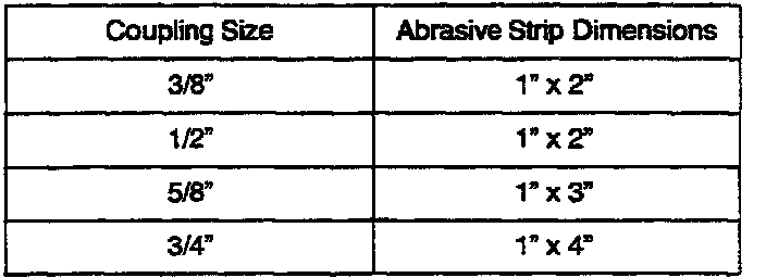
^ Abrasive Strip (Maroon colored 3M "Scotch Brite") pad cut into strips as shown.
^ 3-1/2" length of steel welding rod
^ Mineral oil for R-12 systems and PAG oil for R-134a systems
^ Variable speed electric drill
^ Safety glasses or goggles
^ Lint free cloth
^ 12" length of natural fiber string
NOTE:
Obtain materials locally.
COUPLING CLEANING PROCEDURES
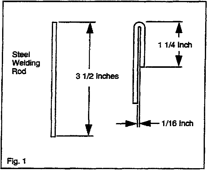
a) Bend the welding rod to fabricate a cleaning tool. Refer to Fig. 1.
b) Determine coupler size and select appropriate length of abrasive strip.
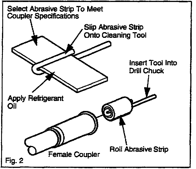
c) Insert strip into cleaning tool. Refer to Fig. 2
d) Insert tool into drill chuck and secure.
e) Coat the abrasive strip with the appropriate refrigerant oil.
f) Roll abrasive strip around cleaning tool. Refer to Fig. 2.
g) Use the variable speed drill in the low setting and slowly insert the cleaning assembly into the coupling.
^ Clean at moderate speed for approximately one (1) minute or until the surface is clean.
CAUTION:
Maintain low drill speed while moving the cleaning assembly from the coupling. This will prevent axial scratches and possible future leaks.
Do not allow drill to exceed 1500 rpm, tool separation may occur.
h) Remove any residue with a lint free cloth.
NOTE:
To prevent material fibers from remaining on the sealing surface, a lint free cloth is needed.
i) Inspect the sealing surface for grooves. If grooves can not be removed, replace the component.
5. Inspect the male coupling for:
^ sealing surface scratches
^ corrosion
^ 0-ring debris
6. Remove any surface residue using the following procedure.
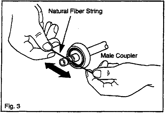
a) Loop the natural fiber string around the coupling and clean the sealing surface as shown. Refer to Fig. 3.
NOTE:
To prevent material fibers from remaining on the sealing surface, natural fiber string is needed.
7. Assemble lock spring coupling.
NOTE:
Use only new green 0-rings. Using any 0-ring other than specified may allow connection to leak intermittently during operation.
^ Lubricate new 0-ring seals using the appropriate refrigerant oil.
^ Install 0-rings.
^ Lubricate inside of female coupling using appropriate refrigerant oil.
^ Install plastic indicator ring into cage opening if indicator ring is to be used.
^ Fit female coupling to male coupling and push with a twisting motion until the garter spring snaps over the flared end of the female fitting.
NOTE:
If the plastic indicator ring is used, it will snap out of the opening when the coupling is connected to indicate engagement. If the indicator ring is not used, check the coupling engagement by verifying that the garter spring is over the flared end of the female coupling.
8. Repeat procedure as necessary.
9. Recharge system and leak test to verify repair.
^ If coupling continues to leak, replace the component.

DISCLAIMER