Assembly
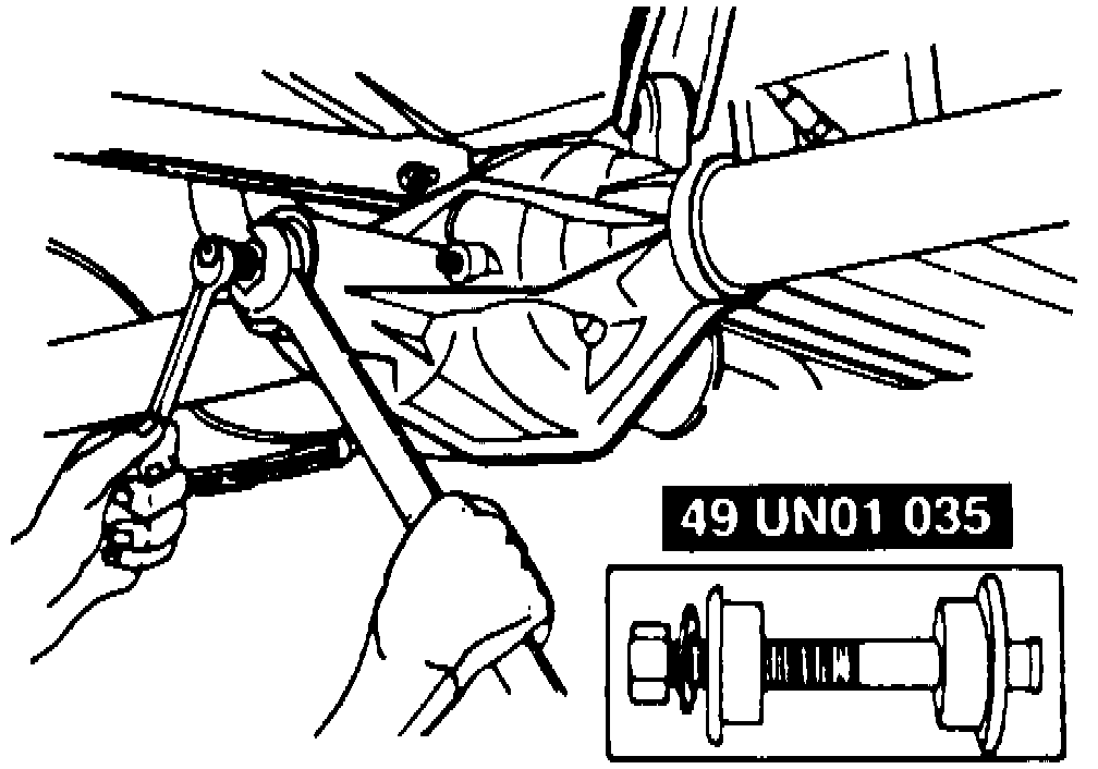
1. Install new pinion bearing races using pinion bearing cup replacer tool No. 49 UN01 035, or equivalent, Fig. 43.Fig. 43 Pinion Bearing Race Installation:
2. Select a new oil slinger/selective shim using pinion depth gauge tool No. T79P-4020-A, or equivalent, and proceed as follows:
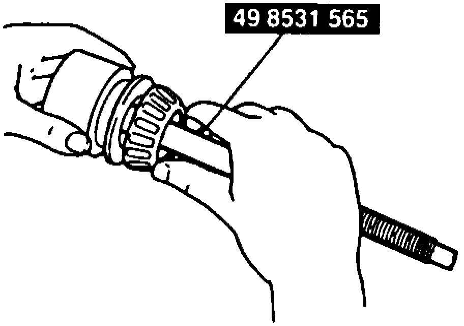
a. Install the original oil slinger and rear bearing onto pinion model No. 49 8531 565, or equivalent, Fig. 44.
Fig. 44 Oil Slinger/Selective Shim Installation:
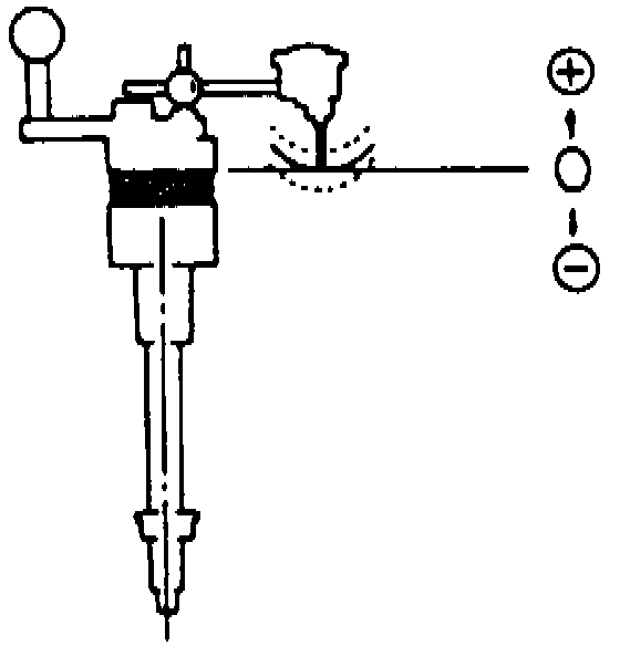
b. Install O-ring on collar (B) tool No. 49 UN27 004, or equivalent, and place tool in axle casing, Fig. 45.
Fig. 45 Pinion Bearing Preload Tool Installation:
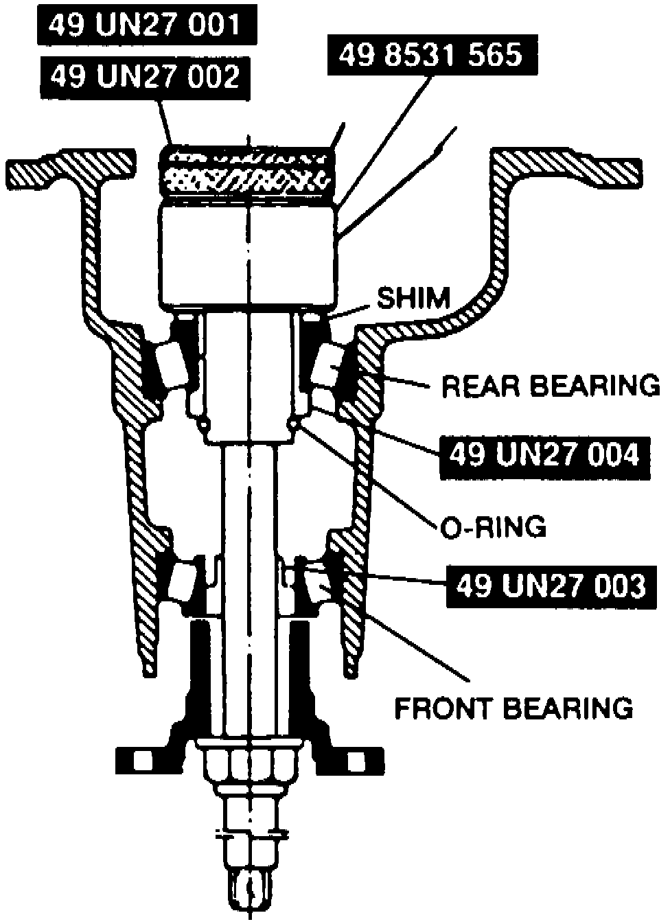
c. Install collar (A) tool No. 49 UN27 003, or equivalent, yoke and washer.
d. Tighten nut on pinion model tool No. 49 8531 565, or equivalent, then confirm that yoke will rotate freely by hand.
e. Install gauge block tool Nos. 49 UN27 001 and 49 UN27 002, or equivalents, onto pinion model tool No. 49 8531 565, or equivalent.
f. Place pinion model assembly on a surface plate and set dial indicator to zero.
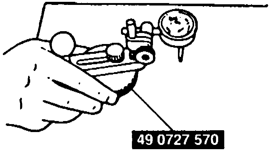
g. Place dial indicator on top of gauge block tool No. 49 UN27 001, or equivalent, and place pointer so it contacts side installed in housing, Fig. 46.
Fig. 46 Dial Indicator Installation:
h. Measure lowest position on right and left sides of the case, add measurements together and divide by two, to obtain thickness dimension. The thickness specification is 0, Fig. 47.
Fig. 47 Side Casing Measurement:
i. If measurement is not within specification, adjust pinion height by selecting the proper shim. If drive pinion is marked with a plus sign (+) reading, this amount must be subtracted from the thickness dimension. If the pinion is marked with a minus sign (-) reading, this amount must be added to the thickness dimension.
j. Measure oil slinger/selective shim with a micrometer to verify thickness.
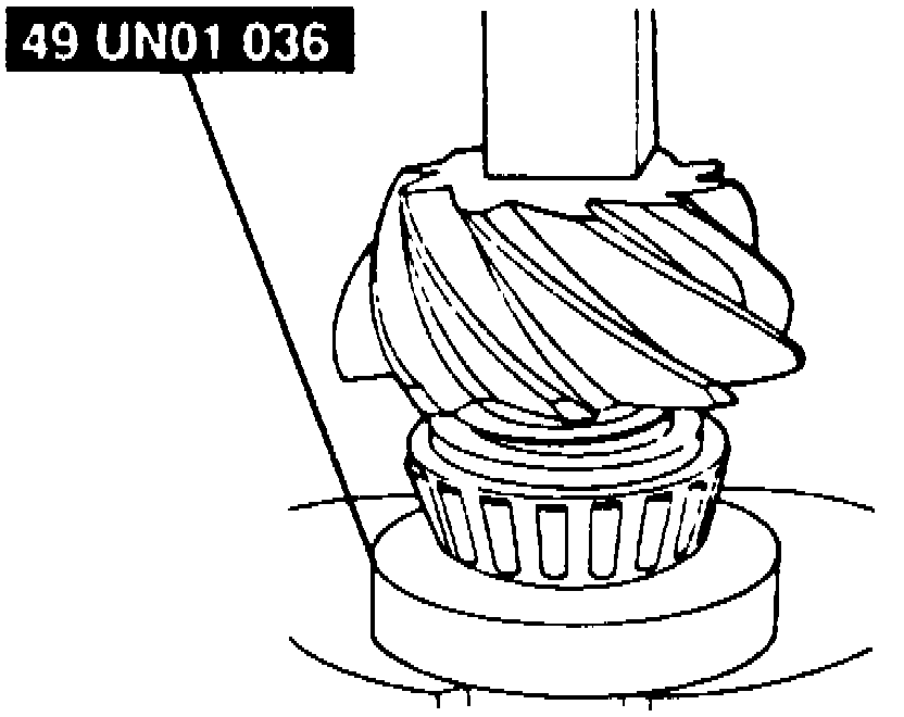
3. Place selective shim on drive pinion, then press rear bearing on pinion, using pinion bearing cone replacer tool No. 49 UN01 036, or equivalent, Fig. 48.
Fig. 48 Bearing Installation:
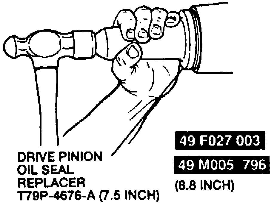
4. Install oil seal onto drive pinion using oil seal replacer tool No. T79P-4676-A, Fig. 49, or equivalent, on models equipped with 7.5 inch ring gear or pinion seal replacer tool Nos. 49 F027 03 and 49 M005 796, or equivalents, on models equipped with 8.8 ring gear. Coat lip of seal with grease.
Fig. 49 Oil Seal Installation:
5. Place a new collapsible spacer onto drive pinion and install pinion in carrier.
6. Install outer pinion bearing and thrust washer or oil slinger.
7. Apply lubricant to drive pinion splines and install companion flange using companion flange replacer tool No. 4858-E, or equivalent, Fig. 12.
Fig. 12 Companion Flange Tool Installation:
8. Rotate pinion gear to ensure bearing is properly seated.
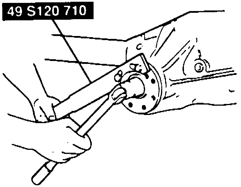
9. While holding companion flange with companion flange holder tool No. 49 5120 710, or equivalent, Fig. 12, install and slowly torque locknut to 170 ft.lb., obtaining frequent rotational torque readings until the reading matches removal rotational torque reading.
10. If the original torque reading is lower than the specification, tighten to specification. If the rotational torque reading is higher than the specification, tighten to the original reading. The specification for used bearings is 8 - 14 in.lb. and 16 - 29 in.lb. for new bearings. Do not back off locknut to reduce rotational torque. If rotational torque reduction is required, a new collapsible spacer and locknut must be installed.
11. Coat pinion gears, side gears and thrust washers with differential oil, then install in axle case.
12. Rotate side and pinion gears until holes in thrust washers and pinion gears line up exactly with holes in the case.
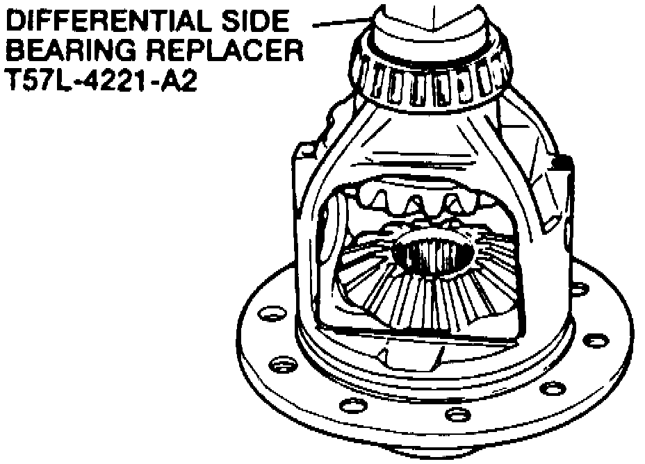
13. Install side bearings onto gear case hub using differential side bearing replacer tool No. T5L-4221-A2, or equivalent, Fig. 50.
Fig. 50 Side Bearing Installation:
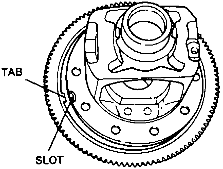
14. Install speed sensor ring and ring gear onto gear case, Fig. 51, aligning tab on sensor ring to slot in gear case.
Fig. 51 Speed Sensor Installation:
15. Press ring gear and speed sensor ring on the gear case using ring gear as pilot.
16. Coat bolt threads with sealant and torque to 85 ft.lb. in a crisscross pattern.
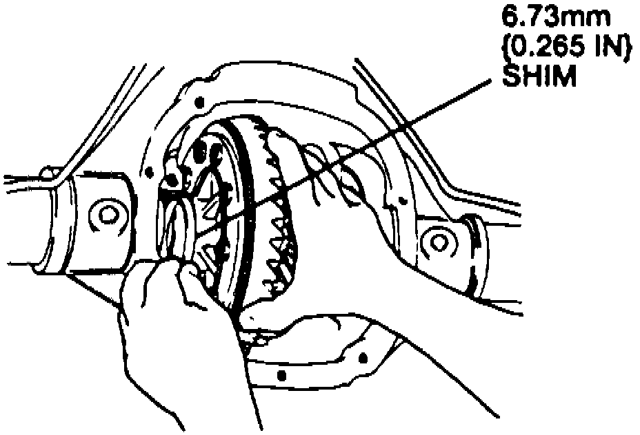
17. Install 0.265 inch shim on left side differential hub, Fig. 52 and place differential gear assembly into axle case.
Fig. 52 Left Side Bearing & Shim Installation:
18. Install left bearing cap bolts finger tight.
19. While applying pressure to left side of differential gear assembly, install progressively larger hub bearing shims on the right side until the largest selected shim produces a slight drag, refer to Fig. 18, 19, 53 and 54.
Fig. 53 Right Side Bearing & Shim Installation:
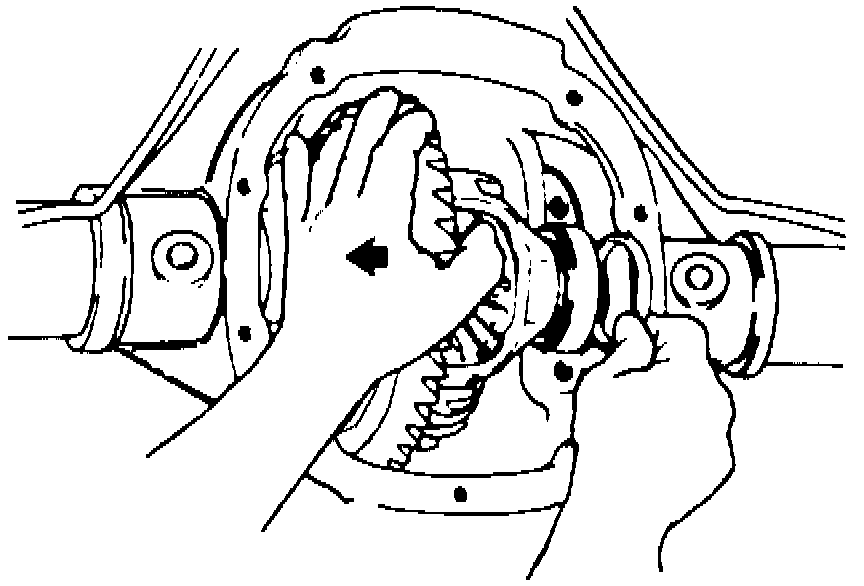
Fig. 54 Ring Gear And Pinion Backlash Adjustment:
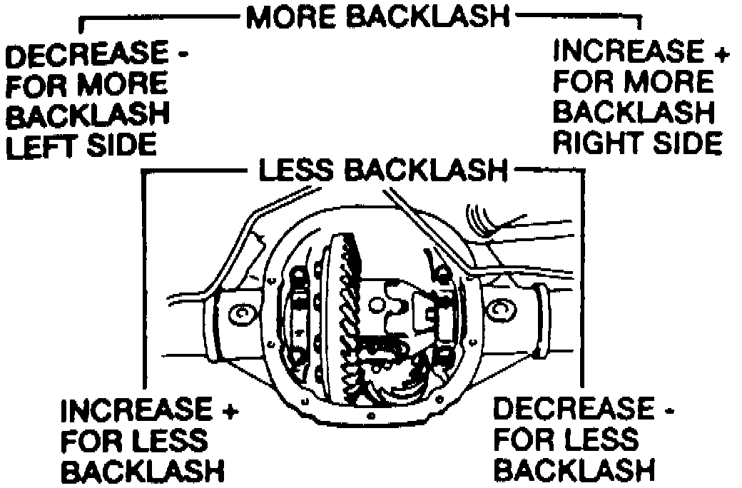
Fig. 18 Backlash Specifications:
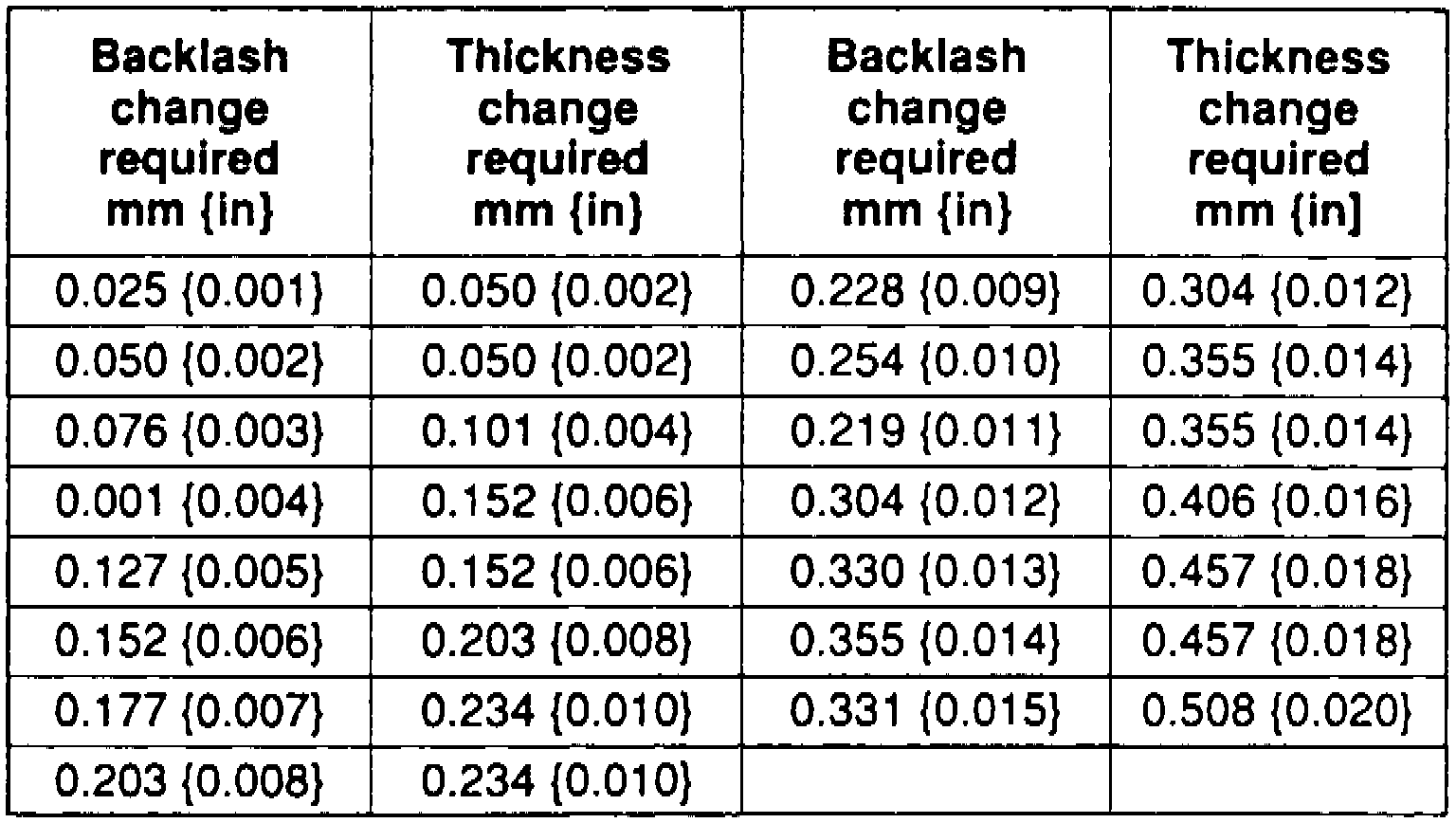
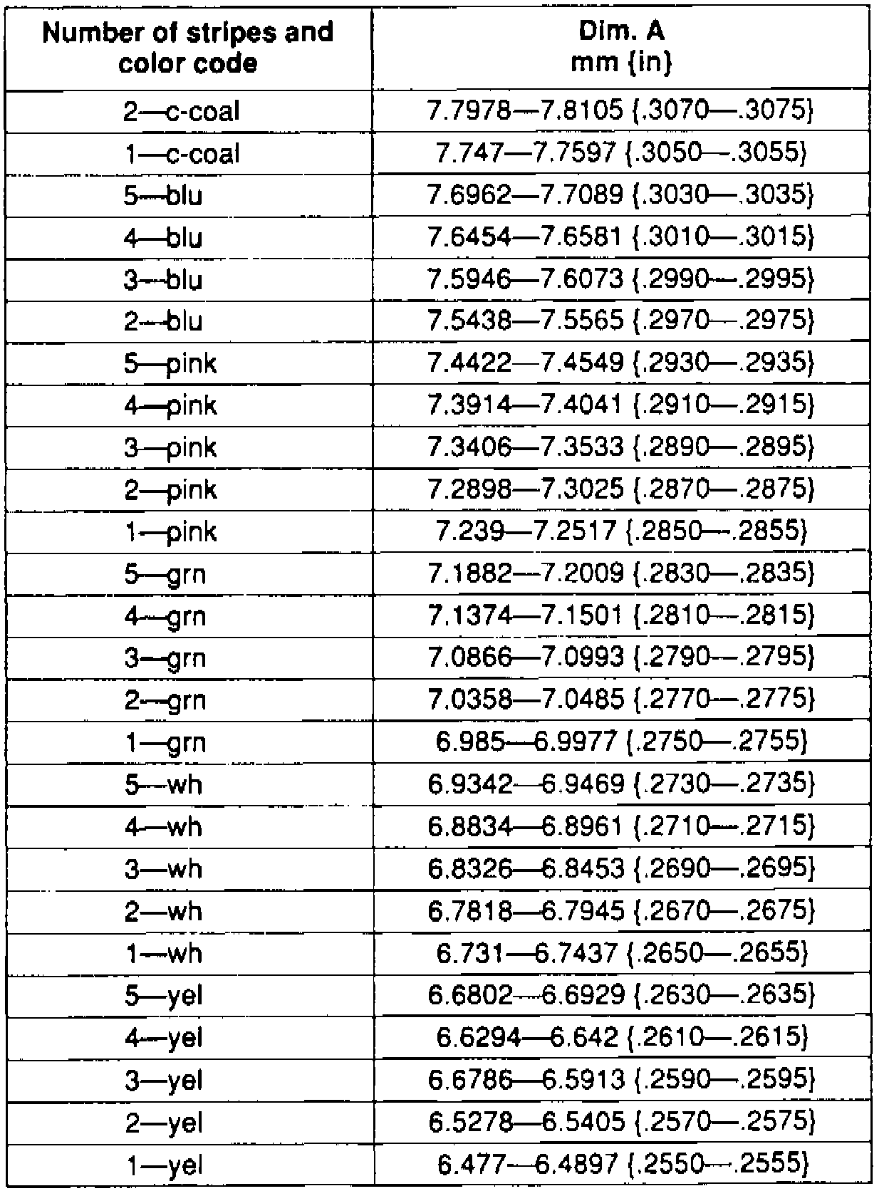
Fig. 19 Side Bearing Shim Code Chart:
20. Install right side bearing cap, then torque both bearing caps to 85 ft.lb., then check for free gear assembly rotation.
21. Check ring gear and pinion backlash; refer to Fig. 19 for backlash specifications. The preferred backlash specification is 0.012 - 0.015 inch and the standard is 0.008 - 0.015 inch. If backlash is out of specification range refer to "Backlash Adjustment".
22. If backlash is within specification, Fig. 18, then establish bearing preload, Fig. 19 and 21.
Fig. 21 Side Bearing Preload Establishment:
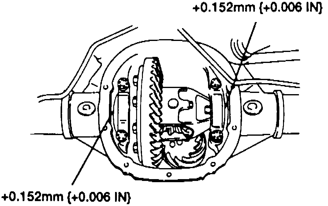
23. Remove bearing caps and bolts, then increase both left and right shim sizes by 0.006 of an inch. Make sure shims are fully seated and gear assembly turns freely.
24. Install bearing caps and torque to 85 ft.lb.
25. Ring gear tooth contact can be inspected at this time by applying a coat of red lead to the ring gear and proceeding as follows:
a. Coat both surfaces of six to eight teeth of the ring gear with a even thin coat of red lead.
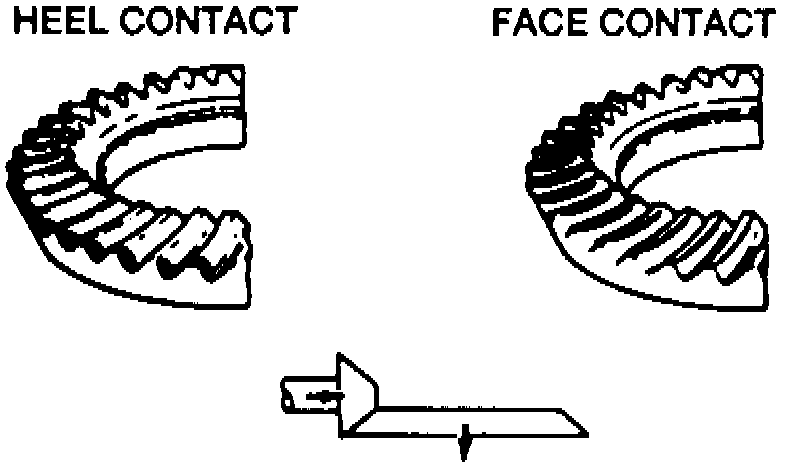
b. Move ring gear back and forth by hand and rotate drive pinion several times and check tooth contact Fig. 22, 55 and 56.
Fig. 22 Ring Gear Contact View:
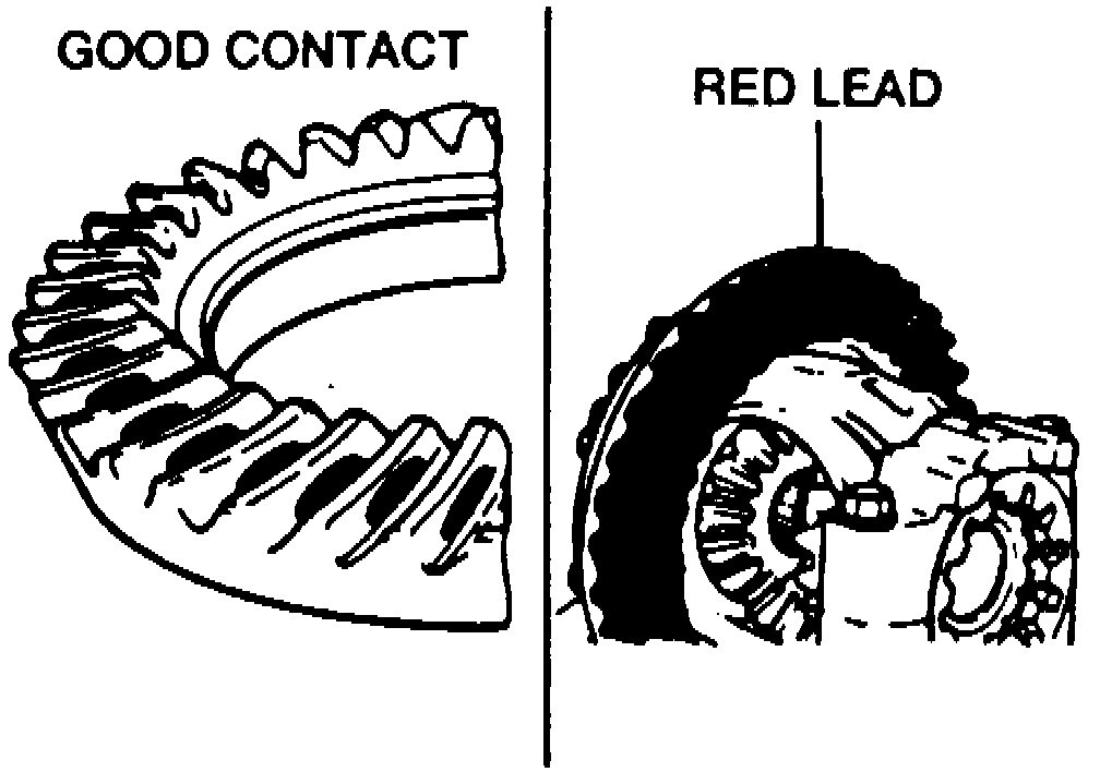
Fig. 55 Toe & Flank Contact View:
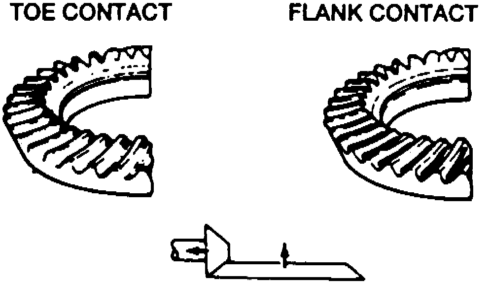
Fig. 56 Heel & Face Contact View:
c. If tooth contact is correct, wipe off red lead coating.
d. If not correct, adjust pinion height and then backlash.
e. For toe and flank contact, replace oil slinger/selective shim with a thinner one, and move drive pinion outward. Refer to Fig. 55.
f. For heel and face contact, replace oil slinger/selective shim with a thicker one, and bring the drive pinion in closer, refer to Fig. 56.