Valve Body: Service and Repair
On-vehicle Removal
WARNING: The ATF is hot; Be careful when draining.
1. Disconnect the negative battery cable.
2. Clean the transmission exterior thoroughly with a steam cleaner or cleaning solvents.
3. On level ground, jack up the vehicle and support it evenly on safety stands.
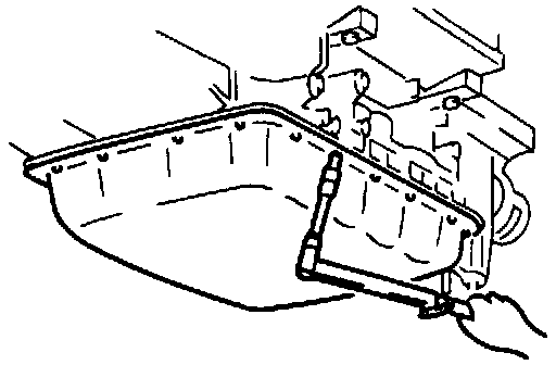
4. Loosen the oil pan bolts and drain the ATF into a suitable container.
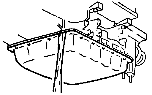
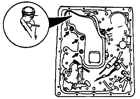
5. Remove the oil pan and gasket.
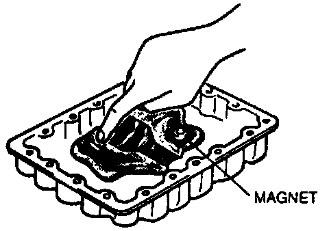
6. Remove the magnet from the oil pan and examine any material found in the pan or on the magnet to determine the condition of the transmission.
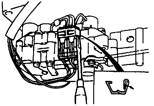
7. Remove the clip.
8. Disconnect the lockup solenoid valve connector.
9. Remove the ATF thermosensor.
Bolt length (measured from below bolt head):
45 mm (1.8 in)
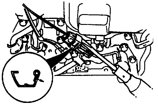
10. Remove the oil strainer.
Bolt length (measured from below bolt head):
50 mm (2.0 in)
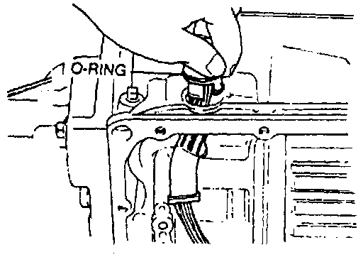
11. Remove the 0-ring from the oil strainer.
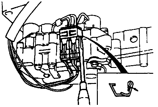
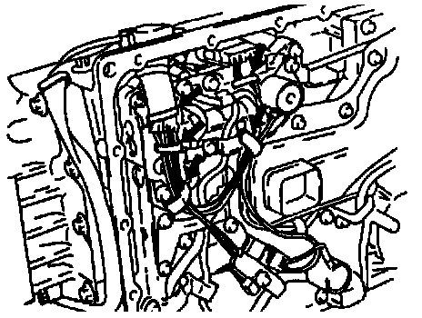
12. Separate the solenoid valve harness from the harness clip.
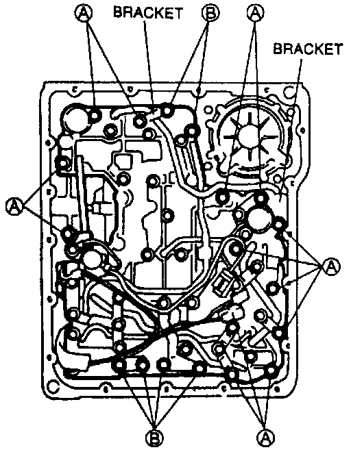
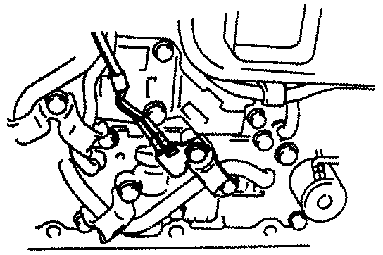
13. Remove bolts A and B and the brackets shown in the figure.
Bolt length (measured from below bolt head):
A: 33 mm (1.3 in)
B: 45 mm (1.8 in)
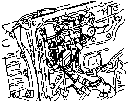
14. Remove the clip.
15. Disconnect the solenoid valve connectors.
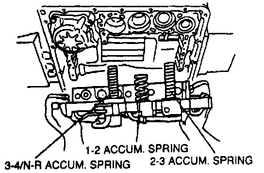
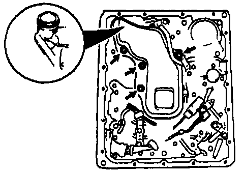
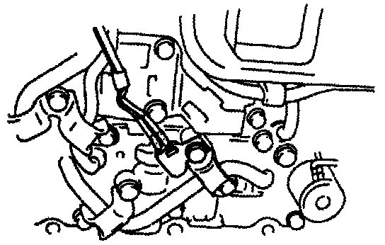
16. Carefully remove the control valve body assembly and accumulator springs.
17. If necessary, remove the solenoid valve harness from the transmission case.
18. Remove the 0-ring from the solenoid valve harness.
On-Vehicle Installation
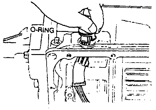
1. Apply ATF to the new 0-ring and install it onto the solenoid valve harness.
2. Install the solenoid valve harness into the transmission case.
3. Connect the solenoid valve connectors.
4. Install the clip.
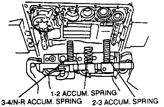
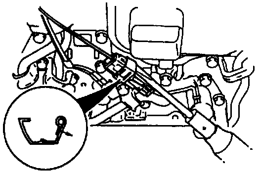
5. Set the accumulator springs into the control valve body as shown.
mm {in.}:
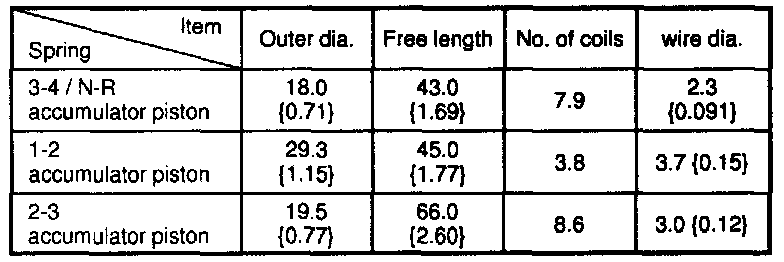
Spring Specifications
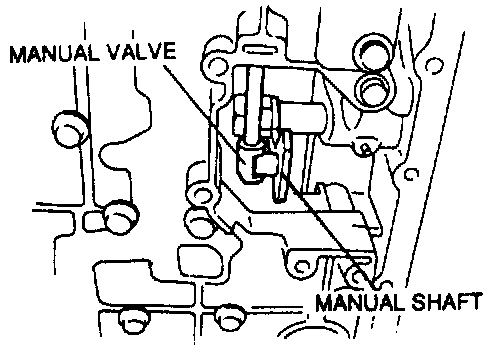
6. Verify that the manual valve and manual shaft are assembled correctly.
7. Set the control valve into the transmission case and secure it.
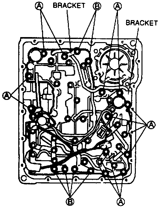
8. Install the A and B bolts and bracket as shown in the figure.
Bolt length (measured from below bolt head):
A: 33 mm (1.3 in)
B: 45 mm (1.8 in)
Tightening Torque: 6.9-8.8 Nm (61-78 in.lb.)
9. Apply ATF to a new 0-ring and install it onto the oil strainer.
10. Install the oil strainer.
Bolt length (measured from below bolt head):
50 mm (2.0 in)
Tightening Torque: 6.9-8.8 Nm (61-78 in.lb.)
11. Secure the solenoid valve harness with the harness clip.
12. Install the ATF thermosensor.
Bolt length (measured from below bolt head):
45 mm (1.8 in)
Tightening Torque: 6.9-8.8 Nm (61-78 in.lb.)
13. Connect the lockup solenoid valve connector.
14. Install the clip.
15. Clean the oil pan and the magnet, and set the magnet into the oil pan.
16. Remove any old locking compound from the bolt holes.
17. Install a new gasket and the oil pan.
18. Tighten the new bolts evenly and quickly.
Tightening Torque: 6.9-8.8 Nm (61-78 in.lb.)
19. Connect the negative battery cable.
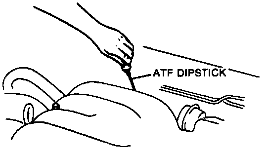
20. Refill the transmission with ATF to the proper level.