Pinout Values and Diagnostic Parameters
Inspection
1. Remove the ECM.
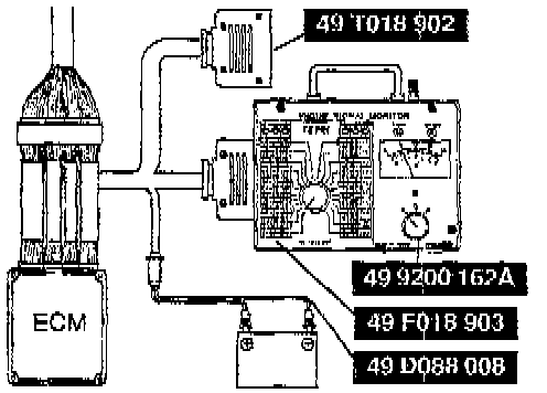
2. Connect the SST (Adapter harness) to the ECM connector.
CAUTION: Applying voltage to SST (Monitor, Engine Signal) terminals A and B will damage the SST.
3. Connect the SST (Monitor, Engine Signal) to the SST (Adapter harness) as shown in the figure.
Use connector A of the adapter harness for ECM terminals 1A through 1V, and 3A through 3R Use connector B for ECM terminals 2A through 2L, and 4A through 4Z.
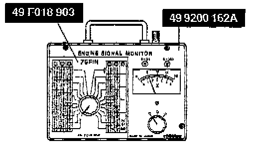
4. Place the SST (Sheet) on the SST (Monitor, Engine Signal).
5. Measure the voltage at each terminal of the ECM.
6. If there is incorrect voltage, check related input or output devices and wiring. If they are OK, replace the ECM.
Terminal voltage (Reference)
ECM Connector View:

Terminal 1A Through 1L:

Terminal 1M Through 2J:

Terminal 2K Through 3M:

Terminal 3N Through 4R:

Terminal 4S Through 4Z:

B+ : Battery positive voltage
*1 : Empty terminal