With Manual Transaxle (G25M-R)
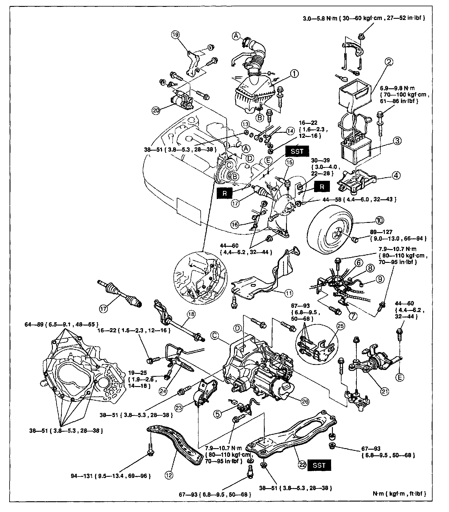
1. Air cleaner assembly
2. Battery box
3. Battery
4. Battery carrier
5. Back-up light switch connector
6. Ground
7. Harness bracket
8. [1][2]Neutral switch
9. Vehicle speedometer sensor connector
10. Wheels and tires
11. Splash shields
12. Transverse member
13. Extension bar
14. Charge control rod
15. Tie-rod ends
16. Stabilizer control links
17. Drive shafts
18. Jointshaft
19. Intake manifold stay
20. Starter
21. No.4 engine mount
22. Engine mounting member
23. No.2 engine mount
24. Clutch release cylinder
25. No.1 engine mount
26. Transaxle
1. Drain the transaxle oil.
2. Remove in the order shown in the image, referring to Removal Note.
3. Install in the reverse order of removal, referring to Installation Note.
4. Add the specified amount and type of transaxle oil. Service and Repair
5. Warm up the engine and transaxle, inspect for oil leakage, and check transaxle operation.
Engine mounting member
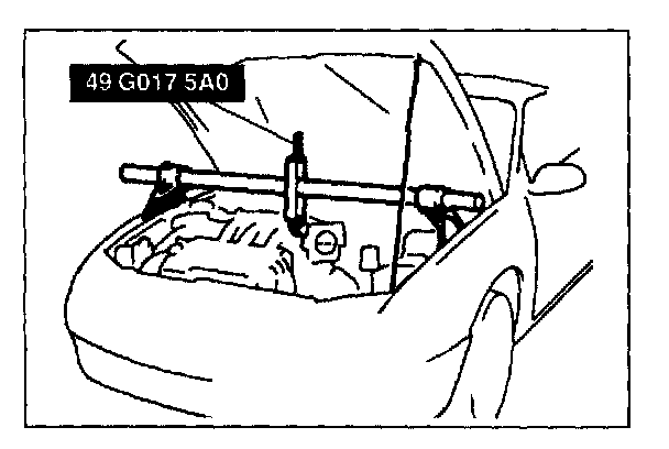
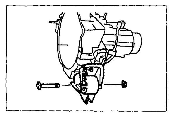
1. Support the engine by using the SST before removing the engine mounting member.
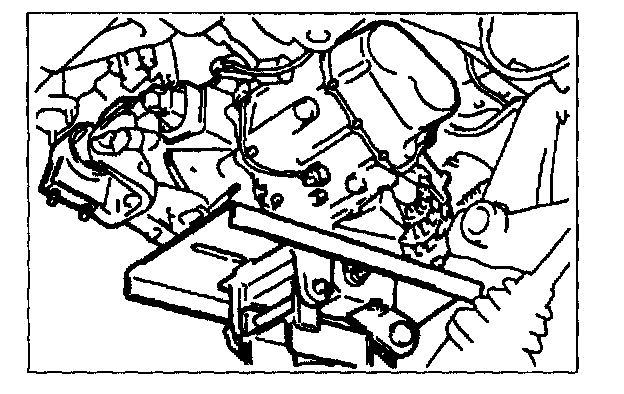
2. Remove the engine mounting member.
Transaxle
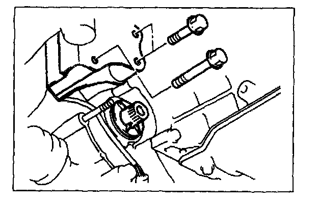
1. Loosen the SST (engine support) and lean the engine toward the transaxle.
2. Support the transaxle on a jack.
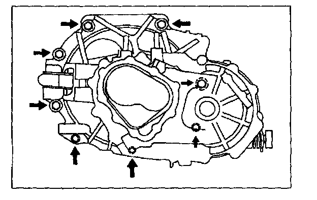
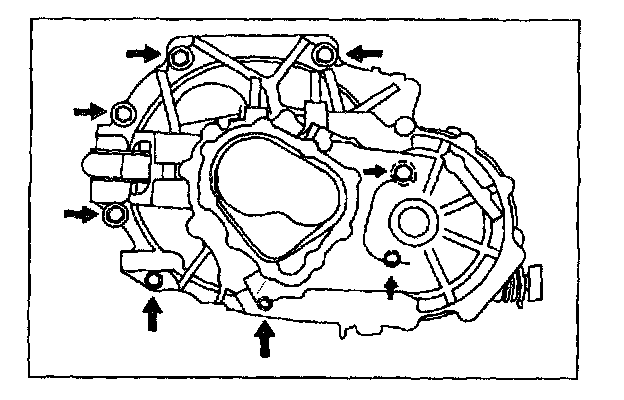
3. Remove the transaxle mounting bolts.
4. Remove the transaxle.
Installation Note
No.2 engine mount
1. Install the No.2 engine mount bracket to the transaxle.
Tightening torque: 38 - 51 N-m (3.8 - 5.3 kgf-m, 28 - 38 ft-lbf)
2. Loosely tighten No.2 engine mount rubber nut.
Transaxle
1. Set the transaxle on a jack and lift into place.
2. Install the transaxle mounting bolts.
Tightening torque: 64 - 89 N-m (6.5 - 9.1 kgf-m, 48 - 65 ft-lbf)
3. Loosely tighten No.4 engine mount bolts and buts.
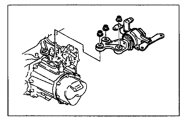
No.1 engine mount
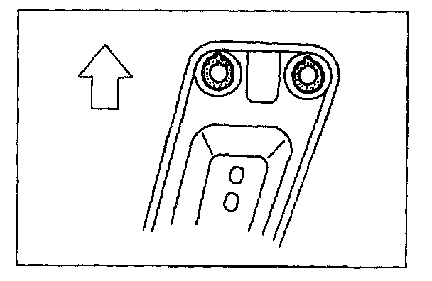
CAUTION: Misaligning the bolts will cause damage to the bolt holes.
1. Use the SST (engine support) to make sure the transaxle bolt holes and No.1 engine mount meet evenly.
2. After the 3 bolts are set in the holes, tighten the bolts to the specified torque.
Tightening torque: 67 - 93 N-m (6.8 - 9.5 kgf-m, 50 - 68 ft-lbf)
Engine mounting member
NOTE:
- Verify that the engine mount rubbers are installed as shown.
- Put the No.1 engine mount stud bolts in the installing holes when installing the engine mounting member.

1. Install the bolts and nuts as shown.
Tightening torque
A: 67 - 93 N-m (6.8 - 9.5 kgf-m, 50 - 68 ft-lbf)
B: 38 - 51 N-m (3.8 - 5.3 kgf-m, 28 - 38 ft-lbf)
2. Tighten the No.2 engine mount rubber nut.
Tightening torque: 67 - 93 N-m (6.8 - 9.5 kgf-m, 50 - 68 ft-lbf)
3. Tighten the No.4 engine mount bolts and nut.
Tightening torque: 67 - 93 N-m (6.8 - 9.5 kgf-m, 50 - 68 ft-lbf)
4. Remove the SST (engine support).