Intake Manifold: Service and Repair
REMOVAL / INSTALLATION1. Disconnect the electrical connector from the following parts:
- Mass air flow sensor
- Intake air temperature sensor
- Throttle position sensor
- Idle air control solenoid
2. Disconnect accelerator cable.
3. Remove in the order shown in the figure, referring to Removal Notes.
4. Inspect all parts and repair or replace as necessary.
5. Install in the reverse order of removal, referring to Installation Note.
1. Air cleaner
2. Air intake hose
3. Throttle body
Upper Intake Manifold Components:
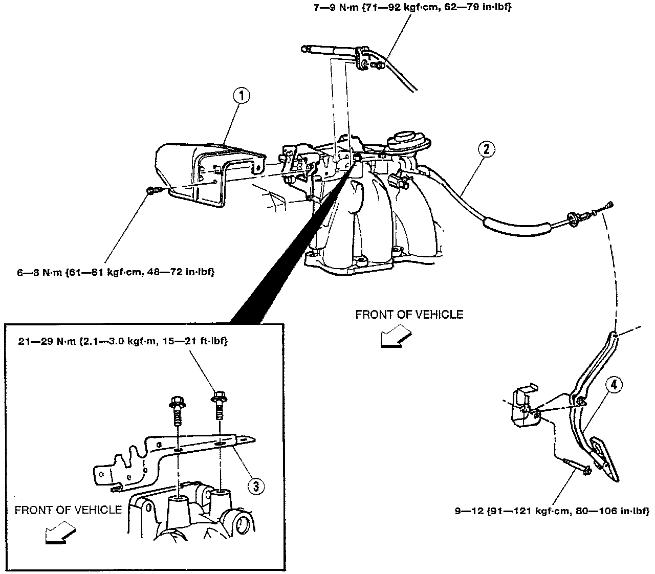
4. Upper intake manifold
5. Fuel rail
6. Fuel injector
7. Intake manifold
REMOVAL NOTES
WARNING: Before performing the following operation, release the fuel pressure from the system to reduce the possibility of injury or fire.
Fuel Line Quick Connect Removal:
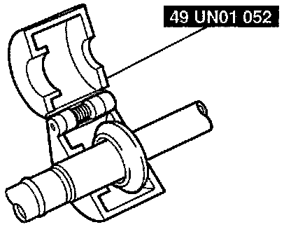
1. Release fuel pressure from the fuel system.
2. Disconnect the fuel supply line using the Special Service Tool SST.
Fuel Line Quick Connect Removal:
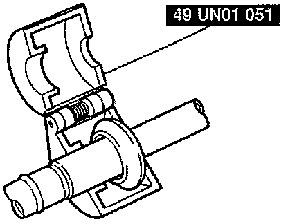
3. Disconnect the fuel return line using the SST.
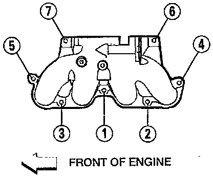
Intake Lower Manifold Torque Sequence:
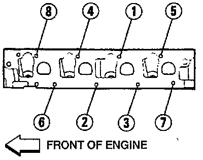
INTAKE MANIFOLD INSTALLATION NOTES
1. Clean and apply a small amount of clean engine oil to all bolts and stud threads before installing them.
2. Install the intake manifold and hand-tighten all the bolts and stud.
3. Tighten the intake manifold bolts and stud in the order shown to the specified torque.
Tightening torque 26-38 Nm (19-28 ft. lbs.)
Intake Upper Manifold Torque Sequence:
UPPER INTAKE MANIFOLD
1. Install the upper intake manifold and hand-tighten all the bolts and studs.
2. Tighten the upper intake manifold bolts and studs in the order shown in two steps.
Tightening torque:
Step 1: 7-10 Nm (61-88 in. lbs.)
Step 2: 26-38 Nm (19-28 ft. lbs.)
INSPECTION
1. Check for damage and cracks.
2. Verify flatness of the manifold contact surface.
3. Replace if necessary.