Assembly
CRANKSHAFT AND REAR OIL SEAL1. Measure main bearing oil clearances as follows:
a. Remove foreign material and oil from journals and bearings.
b. Install upper main bearings and thrust bearing.
c. Install lower main bearings into main bearing caps.
d. Install crankshaft into cylinder block.
e. Position Plastigage on journals.
f. Apply clean engine oil to threads and seat faces of main bearing cap bolts, install caps and tighten to specifications.
g. Remove cap and measure Plastigage at each journal at widest point for smaller clearance, and at narrowest point for largest clearance. Standard clearance is 0.0008-0.0015 inch and maximum clearance is 0.0008-0.0026 inch. If clearance exceeds maximum specifications, grind crankshaft and install undersize bearings.
2. Apply liberal amounts of clean engine oil to main bearings.
3. Apply suitable sealant to rear main bearing caps mounting surface.
4. Seat caps and install bolts. Torque in three steps; first finger tighten until firmly seated, next to 50-59 ft. lbs., finally to 74-84 ft. lbs.
5. Measure crankshaft endplay. Endplay should be 0.004-0.008 inch, with a maximum allowance of 0.012 inch. If endplay exceeds specifications, install oversize thrust bearing, or replace crankshaft and thrust bearing.
6. Install rear oil seal, noting the following:
a. Lubricate rear oil seal and mating surface with clean engine oil.
b. Using rear main seal installation tool No. 49 UN01 070, or equivalent, seat rear oil seal. Rear face of seal must be within 0.005 inch of rear face of engine block.
PISTONS AND CONNECTING RODS
Fig. 18 Engine Assembly Lubrication Points:

1. Oil all pistons, piston rings and cylinder walls before installation, Fig. 18.
2. Check piston rings for correct gap alignment
Fig. 19 Piston Installation:

3. Install piston ring compressor on piston Fig. 19, then push piston into cylinder block with suitable hammer handle until it is slightly below top of cylinder. Guide connecting rod to avoid damaging crankshaft journal. Ensure indentation notch on top of cylinder is toward front of engine. Repeat for remaining pistons.
4. Measure connecting rod bearing oil clearances. Do not rotate crankshaft during measurement. Crankshaft must be in BTDC position.
a. Remove any foreign material and oil from journals and bearings.
b. Install connecting rod bearing onto connecting rod cap.
c. Position Plastigage atop journal.
d. Apply clean engine oil to threads and seat faces of connecting rod cap bolts, install caps and tighten to specifications.
e. Remove cap and measure Plastigage at each journal at widest point for smaller clearance, and at narrowest point for largest clearance. Standard clearance is 0.0008-0.0015 inch and maximum clearance is 0.0008-0.0026 inch. If clearance exceeds maximum specifications, grind crankshaft and install undersize bearings.
5. Install connecting rod bearings and caps, noting the following:
a. Remove Plastigage from journals and bearings and apply liberal amounts of clean engine oil.
b. Turn crankshaft to bottom of throw and seat piston, then install connecting rod cap. Torque bolts in two steps; first to 25-30 ft. lbs., then to 30-36 ft. lbs.
Fig. 20 Connecting Rod Side Clearance:

6. Measure side clearance of each connecting rod on each journal, Fig. 20. Clearance should be 0.0035-0.0105 inch with a maximum of 0.014 inch. If clearance exceeds maximum, replace connecting rod and cap.
OIL PUMP, OIL STRAINER AND OIL PAN
1. Oil all parts thoroughly and install new gasket on oil pump.
2. Install inlet tube to pump and install pump, tube and strainer assembly to engine block.
3. Install oil level sensor to oil pan and affix new oil pan gasket to cleaned surface of engine block.
4. Install oil pan and tighten to specifications.
FLYWHEEL AND CLUTCH
1. Install flywheel and tighten to specifications.
2. Install clutch disc and clean surfaces of clutch cover and flywheel with suitable alcohol base solvent to remove any oil. Do not use petroleum base product or immerse clutch cover in solvent.
3. Position clutch disc on flywheel and use clutch alignment tool No. T74P-7137-K, or equivalent, to align disc.
Fig. 21 Flywheel & Clutch Assembly:
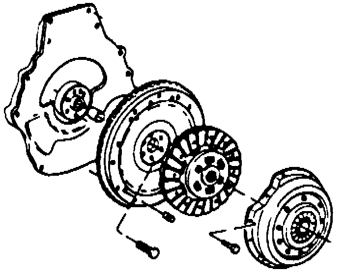
4. Position clutch cover on flywheel and align, then tighten to specifications. Refer to Fig. 21.
DRIVE PLATE
Fig. 23 Drive Plate Installation:

1. Install driveplate reinforcement plate, Fig. 22. Tighten to specifications.
WATER PUMP
1. Position new gasket on water pump using suitable contact cement.
Fig. 22 Water Pump Assembly:
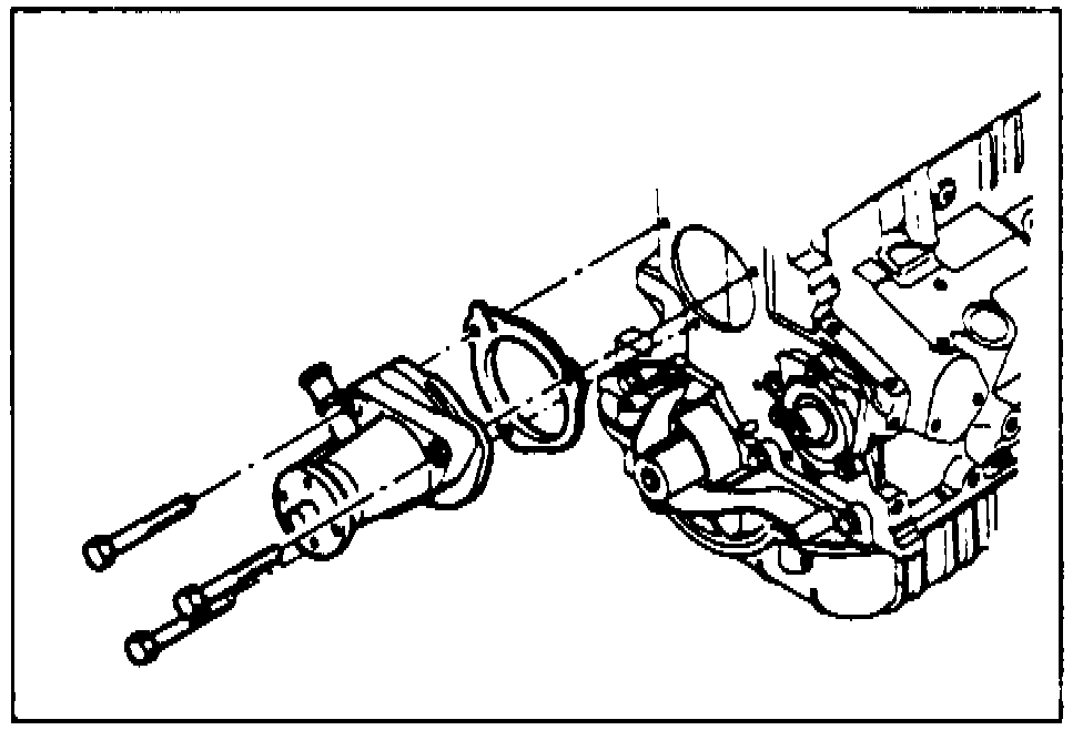
2. Install water pump to cylinder block and install bolts, with sealer applied, to pump, Fig. 24. Tighten to specifications.
AUXILIARY SHAFT AND FRONT COVER
Fig. 24 Auxiliary Shaft & Front Cover Assembly:
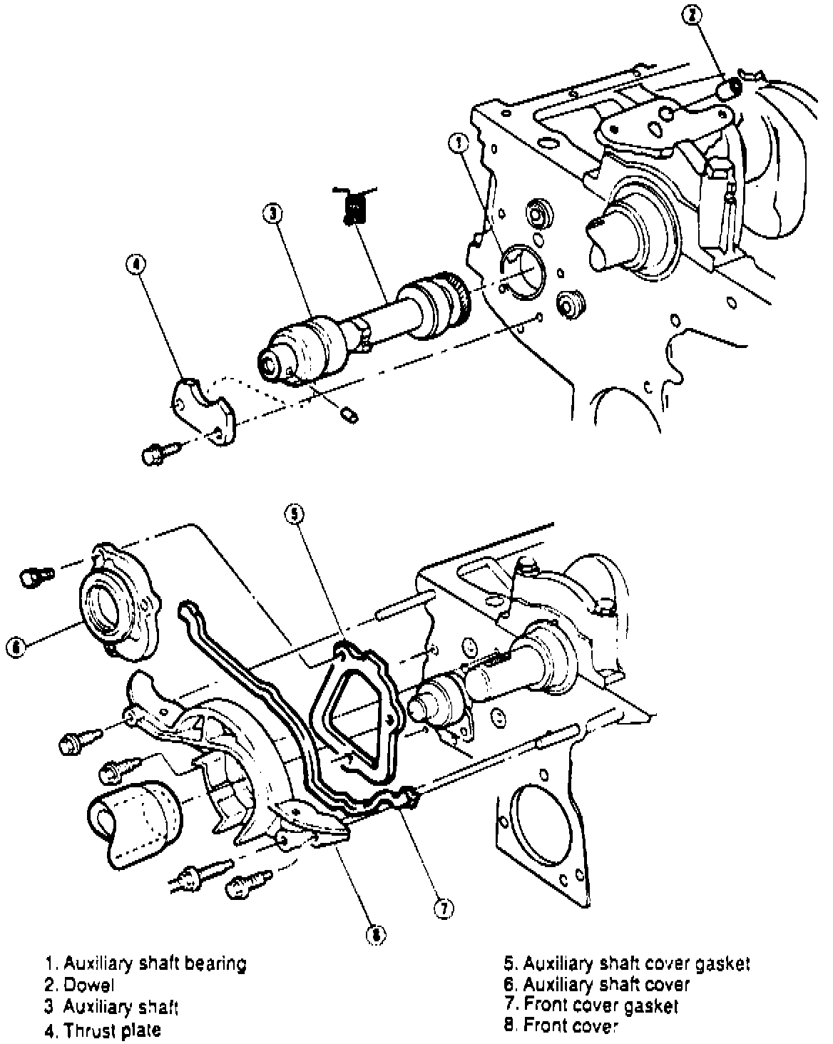
1. Install auxiliary shaft bearing using a suitable bearing driver, Fig. 24. Ensure to align oil holes in bearing with those in cylinder block.
2. Install thoroughly oiled auxiliary shaft into cylinder block, taking care not to let gears touch the bearing surface.
3. Install thrust plate and tighten to specifications.
4. Install auxiliary shaft gasket and cover and tighten to specifications.
5. Install timing belt inner cover and auxiliary shaft pulley.
Fig. 25 Front Cover Installation:
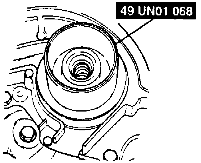
6. Using special tool No. 49 UN01 068, or equivalent, position and adjust front cover to cylinder block to avoid interference from timing belt, Fig. 25. tighten to specifications.
CYLINDER HEAD AND ROCKER SHAFT
1. Install spring and damper assembly. Spring and damper assembly height must be no greater than 1.08 inches. If height is greater than specified, install 0.030 spacer between cylinder head spring pad and spring damper assembly.
2. Install camshaft bearings using bearing installation tool No. T71P-6250-A, or equivalent.
3. Install camshaft into cylinder head making sure that threaded plug is in rear of camshaft. Coat lobes with suitable multi-purpose grease and carefully slide camshaft through bearings into position.
4. Using valve spring compressor tool No. 49 UN01 065, or equivalent, depress valve springs and install keepers.
5. Using same special tool, again depress valve springs and install rocker arms.
6. Install camshaft thrust plate and tighten to specifications.
7. Install camshaft oil seal using seal installation tool No. T74P-6150-P, or equivalent.
8. Install cylinder head as outlined under Cylinder Head Removal and Installation. Cylinder Head Assembly
FRONT HOUSING AND TIMING BELT
1. Install timing belt guide and camshaft pulley on camshaft, then the bolt. Tighten to specifications.
2. Install timing belt tensioner, adjustment bolt and spring bolt. Tighten to specifications.
3. Install timing belt outer cover and tighten to specifications.
4. Install crankshaft pulley and tighten to specifications.
VALVE COVER
1. Using new gasket, install valve covers and tighten to specifications.
ENGINE FINAL ASSEMBLY
1. Install generator mounting bracket, generator, drive belt and drive belt tensioner.
2. Install oil dipstick bracket and tube.
3. Install vacuum hoses and air cleaner assembly.
4. Install ignition coil and bracket, as follows:
a. Mount coil assemblies to bracket, then the bracket to engine.
b. Connect engine wiring harness to coil ensuring that each high tension lead is fully seated and in proper position. Firing order is 1-3-4-2.
5. Install exhaust manifold and torque bolts in two steps; first to 14-15 ft. lbs., finally to 20-29 ft. lbs.
Fig. 26 Intake Manifold Bolt Tightening Sequence:
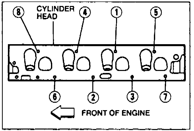
6. Install intake manifold and torque bolts as shown in Fig. 26 in two steps; first to 5-17 ft. lbs., and finally to 15-22 ft. lbs.