Disassembly
PRECAUTIONS1. Clean the transaxle exterior thoroughly with a steam cleaner or cleaning solvent before disassembly.
WARNING: Using compressed air can cause dirt and other particles to fly out, causing injury to the eyes. Wear protective eye-wear whenever using compressed air.
2. Clean the removed parts (except sealed bearings) and all sealing surfaces with cleaning solvent, and dry with compressed air.
3. Clean out all holes and passages with compressed air, and check that there are no obstructions.
Part 1 Of 2:
Part 2 Of 2:
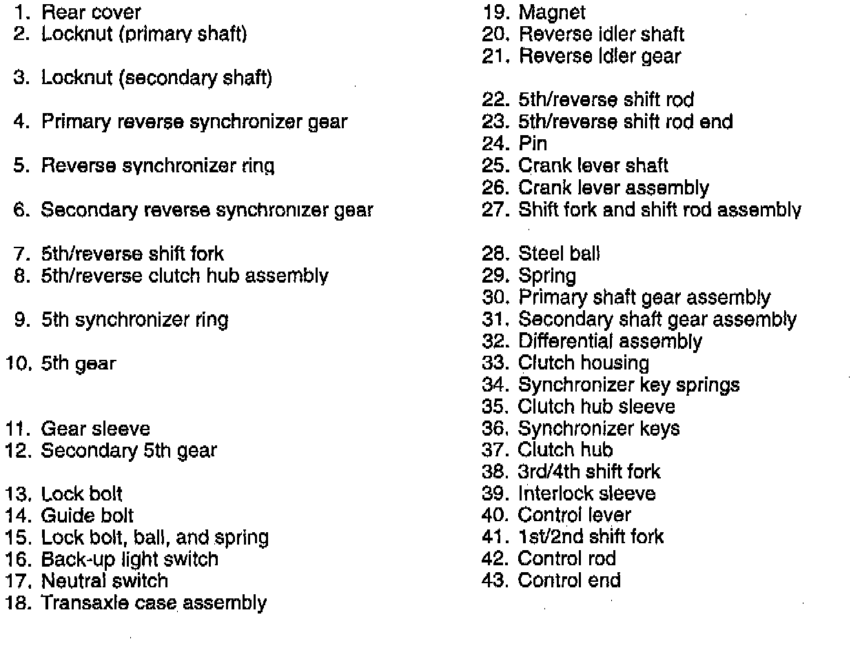
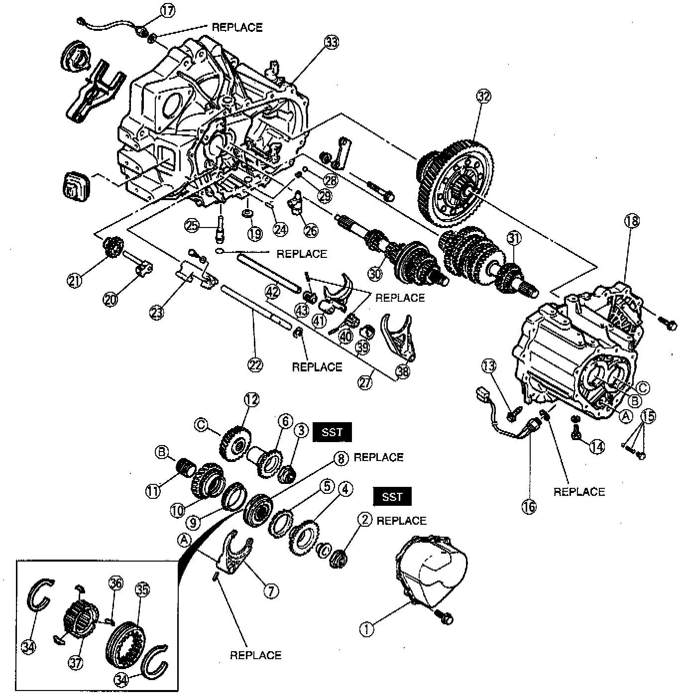
PROCEDURE
- Disassemble in the order shown in the illustration, referring to the following notes:
Locknut
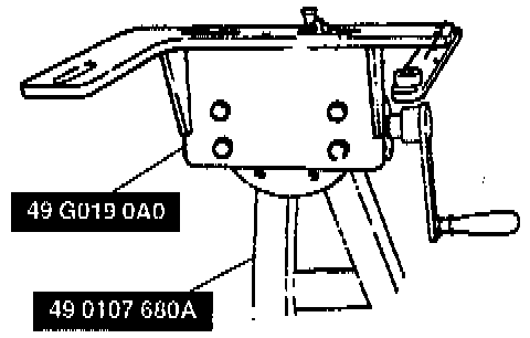
1. Mount the transaxle on the Special Service Tool (SST).
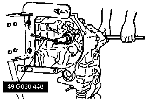
2. Lock the primary shaft with the SST.
3. Shift to 1st gear to lock the rotation of the primary shaft.
4. Uncrimp the tabs of the locknuts.
5. Remove the locknuts from the primary and secondary shafts.
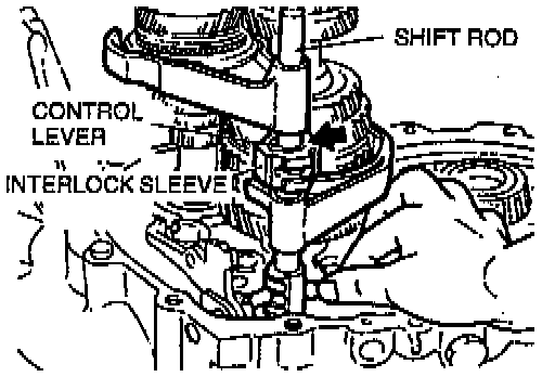
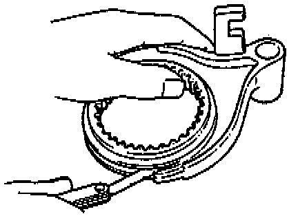
Shift fork and shift rod assembly
1. Align the ends of the interlock sleeve and of the control lever (arrow). Turn the shift rod counterclockwise.
2. While holding the 1st/2nd shift fork with one hand and the 3rd/4th shift fork with the other, raise them both at the same time and shift each of the clutch hub sleeves.
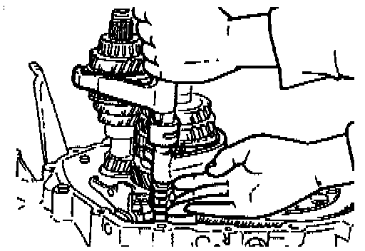
3. Lift the control end and remove the steel ball, and at the same time, remove the control rod from the clutch housing.
4. Separate the shift rod and shift fork assembly from each of the clutch hub sleeves.
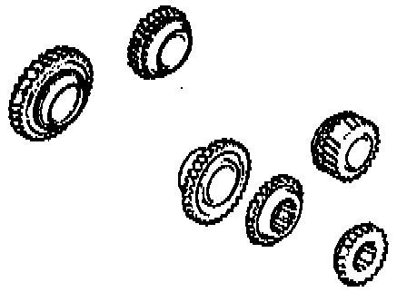
Gears
1. Inspect the synchronizer cones for wear.
2. Inspect the gear teeth for damage, wear, and cracks.
3. Inspect the synchronizer ring matching teeth for damage and wear.
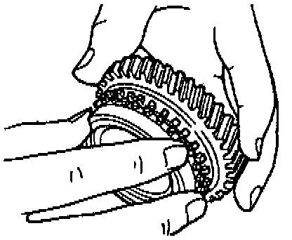
Synchronizer Ring
1. Inspect the synchronizer ring teeth for damage, wear, and cracks.
2. Inspect the tapered surface for wear and cracks.
3. Set the synchronizer ring squarely in the gear.
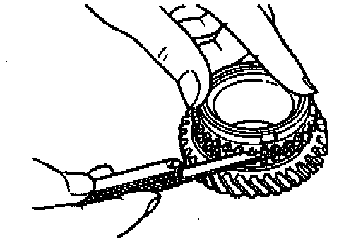
4. Measure the clearance between the synchronizer ring and the flank surface of the gear all around the circumference. Standard clearance is 1.50 mm (0.059 inch) and the minimum is 0.80 mm (0.031 inch).
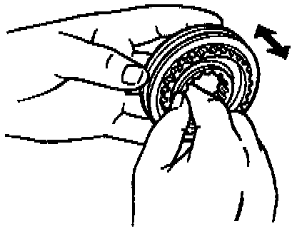
Clutch hub assembly
1. Inspect the clutch hub sleeve and hub operation.
2. Inspect the gear teeth for damage, wear, and cracks.
3. Inspect the synchronizer keys for damage, wear, and cracks.
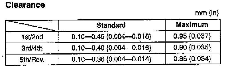
4. Measure the clearance between the hub sleeve and shift fork.