Flow Chart No. 1: Cruise Control Inoperative
Flow Chart No. 1 - Symptom Cruise control inoperative.Step 1
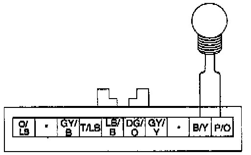
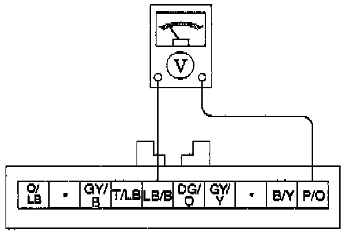
Verify there is power to cruise control servo.
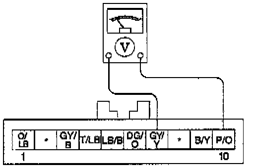
1. Disconnect harness connector from the cruise control servo.
Use voltmeter to make specified measurements at the harness connector. To avoid terminal damage, use a flat-bladed adapter.
2. With the ignition switch in RUN, measure voltage between Pin 7 (GY/Y) and Pin 10 (P/O).
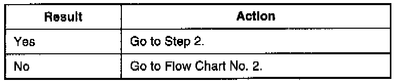
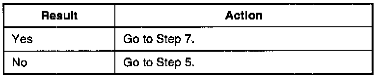
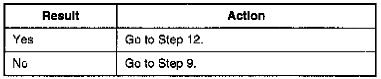
3. Is there battery voltage?
Step 2
Check for stuck brake on/off (BOO) switch.
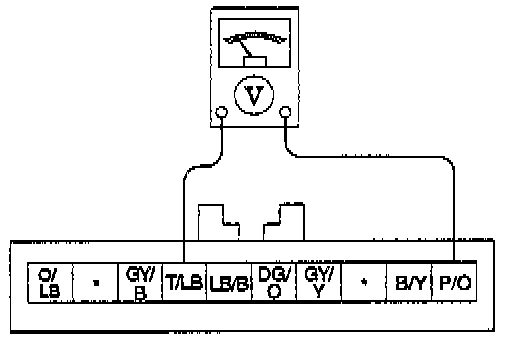
1. With no brakes applied, measure the voltage between Pin 4 (T/LB) and Pin 10 (P/O).

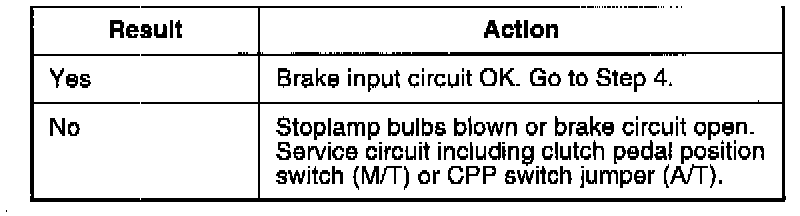
2. Is battery voltage present?
Step 3
Check brake/clutch circuit.

1. With the ignition switch in OFF position, measure the resistance between Pin 4 (T/LB) and Pin 10 (P/O).
2. Is resistance less than 20 ohms?
Step 4
Check deactivator switch circuit.
1. Turn the ignition switch to RUN position.
2. With no brakes applied, place a voltmeter between Pin 9 (B/Y) and Pin 10 (P/O).
3. Is there B+?
Step 5
Verify power at deactivator switch harness connector.
1. Remove wiring harness connector from deactivator switch.
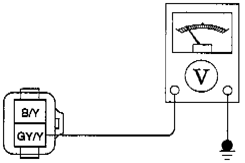
2. Place voltmeter between GY/Y wire of deactivator switch connector and chassis ground.
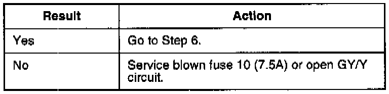
3. Is there B+?
Step 6
Check for open circuit between deactivator switch and cruise control servo.
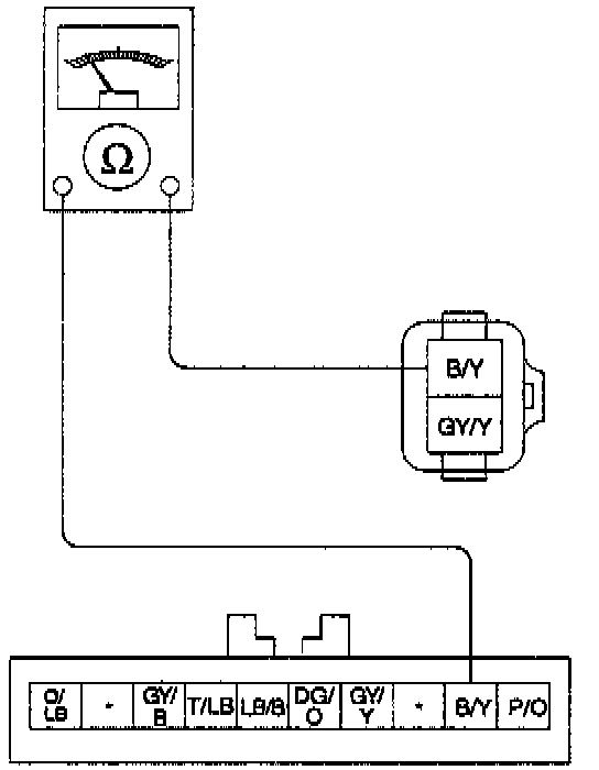
1. Measure resistance of B/Y wire from deactivator switch connector to Pin 9 (B/Y) of cruise control servo connector.
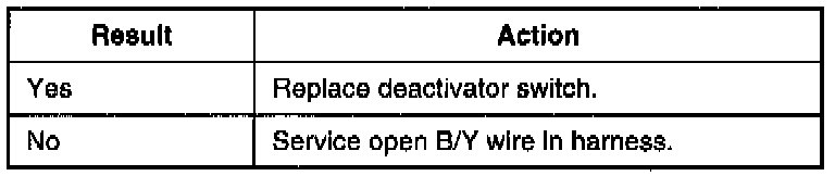
2. Is resistance less than 1 ohm?
Step 7
Check for stuck ON cruise control actuator switch. 1. With no steering wheel switches pressed, measure voltage between Pin 5 (LB/B) and Pin 10 (P/O).
2. Is there battery voltage?
Step 8
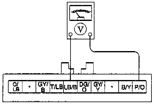
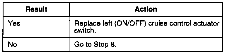
Check ON switch operation.
1. With steering wheel ON switch pressed, measure voltage between Pin 5 (LB/B) and Pin 10 (P/O).
2. Is there battery voltage present?
Step 9
Verify power at air bag sliding contact connector at base of steering column.
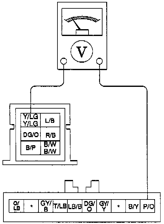
1. Disconnect air bag sliding contact at 6-pin connector at the base of steering column.
2. Measure voltage between Y/LG wire at air bag sliding contact connector on instrument panel harness and Pin 10 (P/O) of cruise control servo connector.
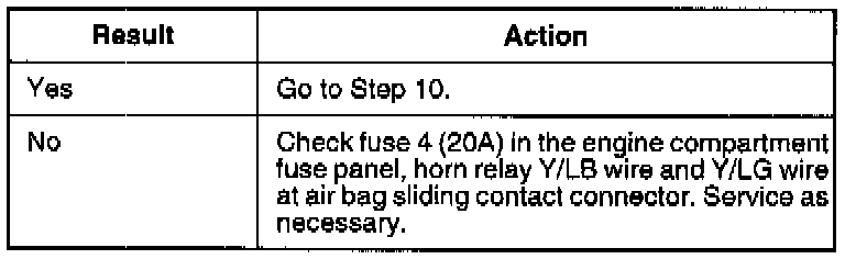
3. Is there battery voltage?
Step 10
Check air bag sliding contact for high resistance.
1. Disconnect cruise control actuator switch 5-pin connector from air bag sliding contact.
2. Measure resistance across each of the air bag sliding contact windings between the air bag sliding contact connector at the base of steering column and cruise control switches connector in steering wheel.
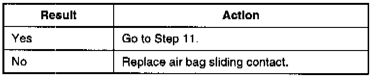
3. Is each resistance reading less than 1.0 ohm?
Step 11
Check for open circuit in steering wheel wiring harness.
1. Reconnect air bag sliding contact assembly at base of steering column.
2. Disconnect connector at ON/OFF switch.
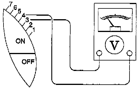
3. Measure voltage between Pin 3 (LB/B) and chassis ground (steering wheel).
4. Is there battery voltage?
Step 12
Check for stuck command switches.
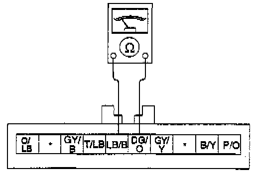
1. With no steering wheel switches pressed, measure resistance between Pin 6(DG/O) and Pin 5(LB/B).
2. Is resistance greater than 3,000 ohms?
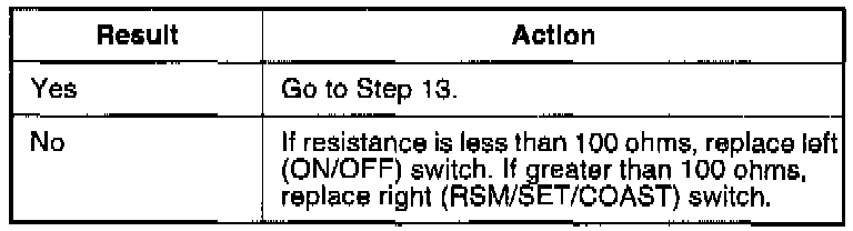
Step 13
Check SET/ACCEL switch operation.
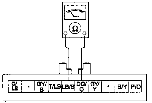
1. With the SET/ACCEL switch pressed, measure the resistance between Pin 5 (LB/B) and Pin 6 (DG/O).
2. Is resistance between 646 and 714 ohms?
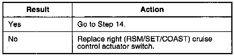
Step 14
Check COAST switch operation.
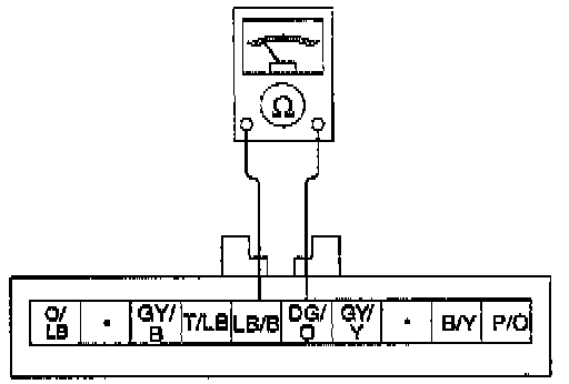
1. With COAST switch pressed, measure resistance between Pin 5 (LB/B) and Pin 6 (DG/O).
2. Is resistance between 114 and 126 ohms?
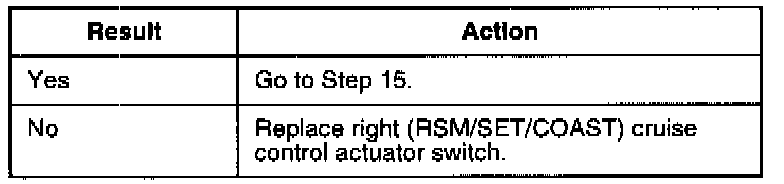
Step 15
Check RESUME switch operation.
1. Disconnect harness connector from cruise control servo assembly.
2. With RESUME switch pressed, measure resistance between Pin 5 (LB/B) and Pin 6 (DG/O).
3. Is resistance between 2090 and 2310 ohms?
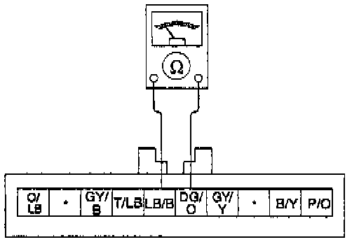
Step 16
Check OFF switch operation.

1. Disconnect harness connector from cruise control servo. With OFF switch pressed, measure resistance between Pin 5 (LB/B) and Pin 6 (DG/O).
2. Is resistance less than 4 ohms?
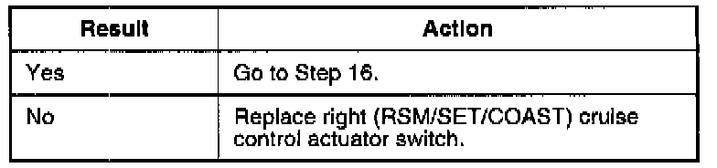
Step 17
Check command switch return circuit.
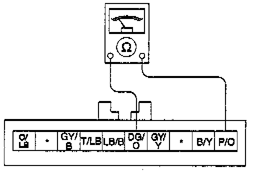
1. Measure resistance between Pin 6 (DG/O) and Pin 10 (P/O).
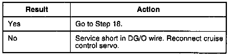
2. Is resistance greater than 1 ohm?
Step 18
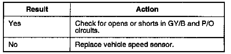
Check vehicle speed sensor (VSS) circuit.
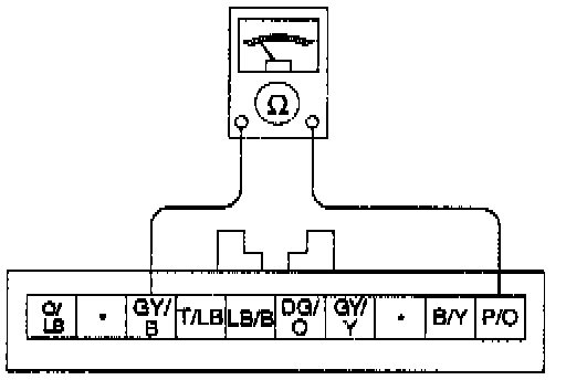
1. Measure resistance between Pin 3 (GY/B) and Pin 10 (P/O).
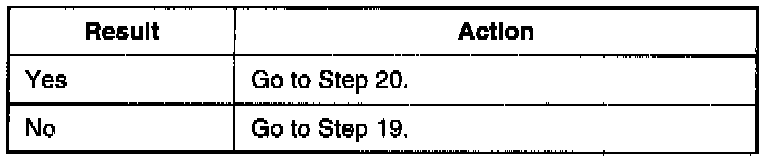
2. Is resistance between 190 and 250 ohms?
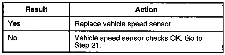
Step 19
Check VSS.
1. Remove VSS connector.
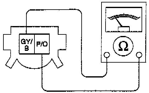
2. Measure resistance across VSS terminals.
3. Is resistance between 190 and 250 ohms?
Step 20
Road test vehicle.
1. Road test vehicle and observe speedometer needle.
2. Does the needle waver?
Step 21
Check for broken or binding cable.
1. Remove cruise control actuator from cruise control servo assembly.
2. Check for broken or binding cable by pulling on cable ball slug to ensure throttle moves freely.
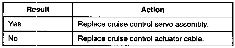
3. Is cable OK?