Disassembly
Part 1 Of 2:

Part 2 Of 2:

DISASSEMBLY
Disassemble in the order indicated in the illustration, referring to disassembly note.
Disassembly Note
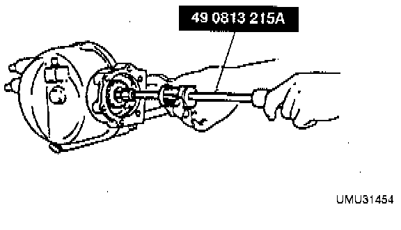
Output Shaft (1)
Remove the output shaft by using the Special Service Tool (SST).
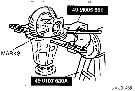
Front Differential Component (4)
1. Mount the differential component on the SSTs.
2. Mark one bearing cap and the carrier.
3. Mark the bearing adjusters for the right and left side.
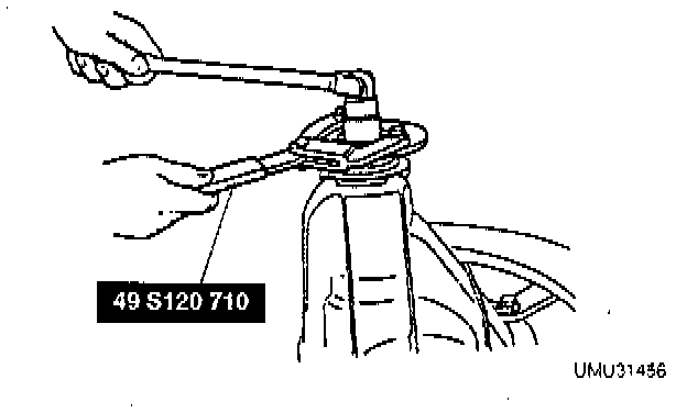
Locknut (10)
Hold the companion flange by using the SST and remove the locknut.
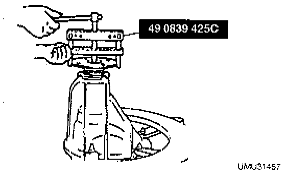
Companion Flange (12)
Remove the companion flange by using the SST.
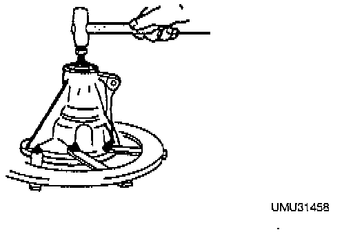
Drive Pinion Component (16)
Push the drive pinion out by attaching a miscellaneous locknut to it, and tapping it with a copper ham
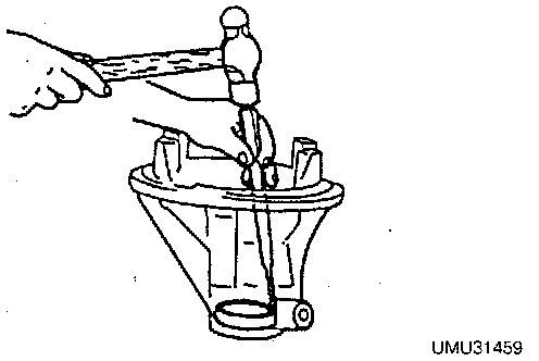
Front and Rear Bearing Race (18, 19)
Mark the bearing races for proper reassembly, and remove them by alternately tapping through the two grooves in the carrier.
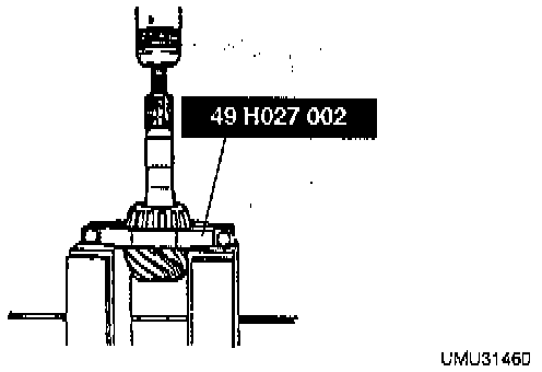
Rear Bearing (20)
While supporting the drive pinion, remove the rear bearing by using the SST.
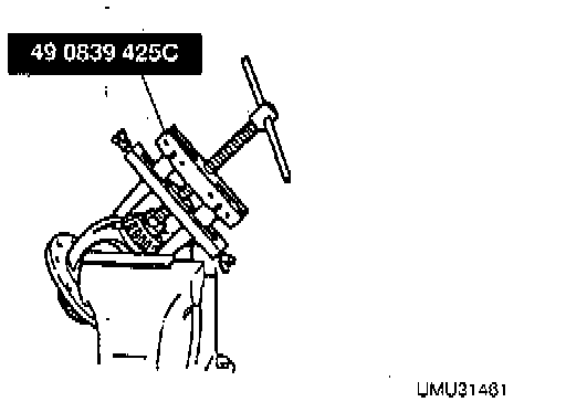
Side Bearing (30)
Mark the bearings for proper reassembly, and move them by using the SST.